

Belt conveyance apparatus and image forming apparatus using such a belt conveyance apparatus
一种带式传送、成像设备的技术,应用在应用电荷图形的电记录工艺、应用电荷图形的电记录工艺的设备、输送机等方向,能够解决从动辊无法随动等问题
- Summary
- Abstract
- Description
- Claims
- Application Information
AI Technical Summary
Problems solved by technology
Method used
Image

Examples
no. 1 example
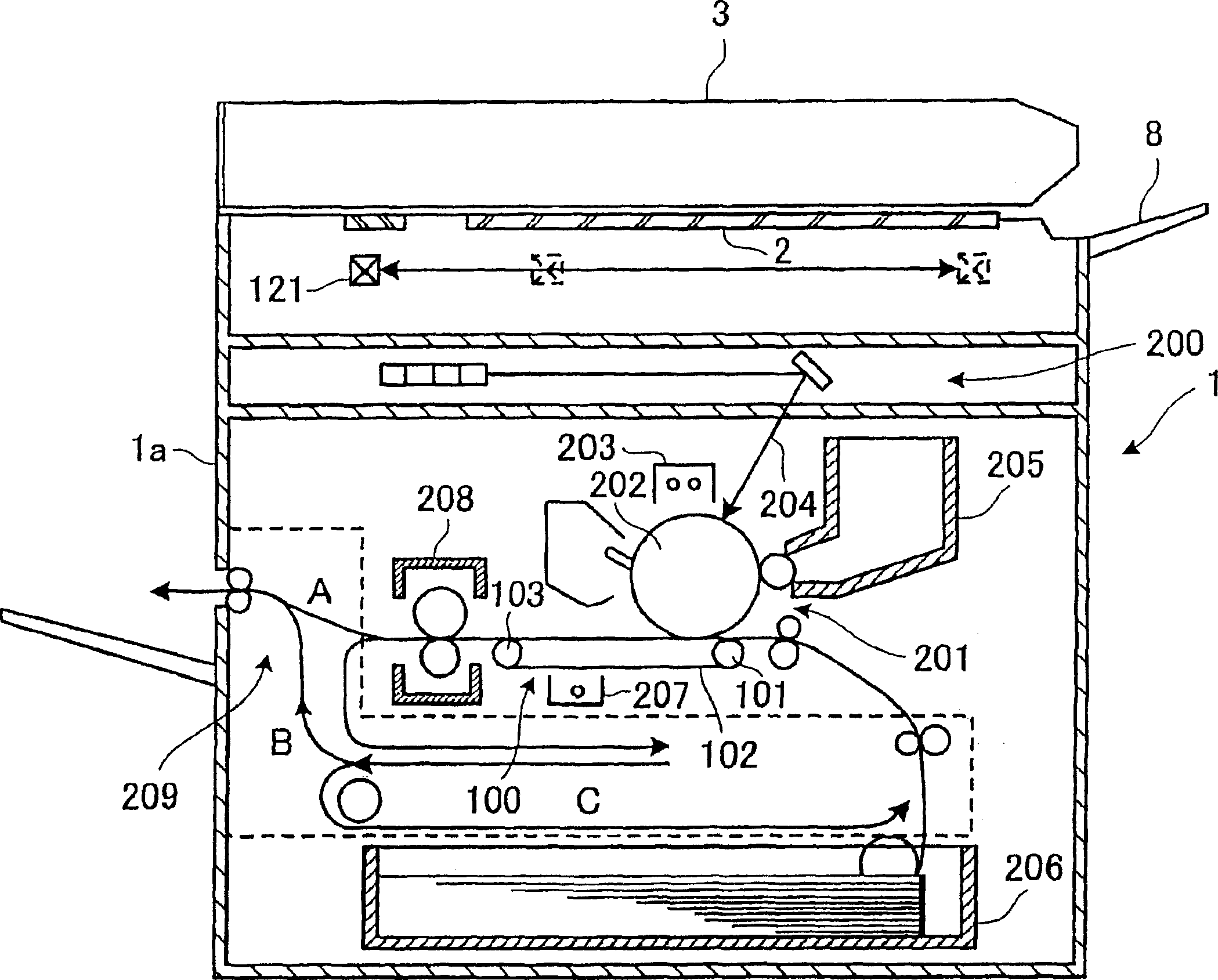
[0048] figure 1 Shown is an overall structure of a digital copying machine as an image forming apparatus to which a belt conveying apparatus according to the first embodiment of the present invention is applied. It is to be noted that the present invention is not limited to digital copiers, but can also be applied to various devices as long as they have a belt conveying unit, such as facsimile devices, printers (including inkjet printers) and the like.
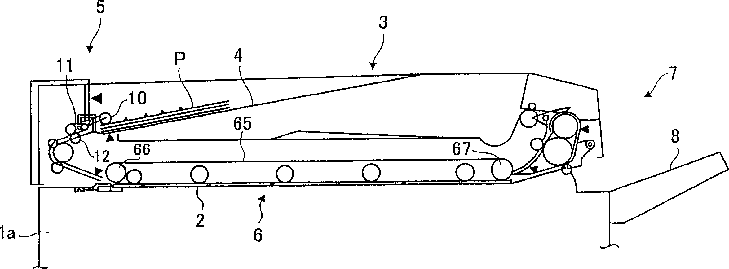
[0049] On the top surface of the main body 1 a of the digital copier 1 are provided a contact glass 2 and a slit glass having a smaller area than the contact glass 2 . In addition, an automatic document feeder 3 (which may be abbreviated as "ADF" hereinafter) is provided on the main body 1a of the digital copying machine 1 (in this example, placed on the contact glass 2 and slotted glass). The ADF 3 is movable relative to the contact glass 2 and the slotted glass to open and close a space above the contact glass 2 and the sl...
no. 2 example
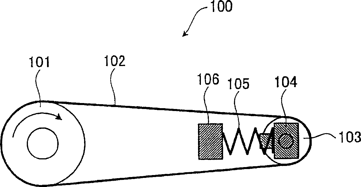
[0072] The digital copying machine according to the second embodiment of the present invention has the same structure as the digital copying machine according to the first embodiment of the present invention except for a part of the intermediate transfer member 100, and thus, figure 1 , 2 , 3 and 5A are used to describe the second embodiment, and the same constituent parts are given the same reference numerals.
[0073] Figure 6 A partial plan view of an intermediate transfer member in a digital copying machine according to a second embodiment of the present invention is shown.
[0074] exist Figure 6 Among them, a groove 110 is formed on the peripheral surface of the intermediate transfer belt driving roller 101 for receiving the flange 107 on the intermediate transfer belt 102 . Here, grooves 110 are formed on both sides of the intermediate transfer belt driving roller 110 in the width direction. It should be noted that in Figure 5A The operation shown in is also app...
no. 3 example
[0080] The digital copying machine according to the third embodiment of the present invention has the same structure as that of the digital copying machine according to the first embodiment of the present invention except for a part of the intermediate transfer member 100, and thus, figure 1 , 2 , 3 and 5A are used to describe the third embodiment, and the same constituent parts are given the same reference numerals.
[0081] Figure 7 A partial plan view of an intermediate transfer member in a digital copying machine according to a third embodiment of the present invention is shown. Figure 8A and 8B A portion of an intermediate transfer belt drive roller with a rotating member is shown. Figure 8C and 8D A portion of an intermediate transfer belt drive roller without a rotating member is shown.
[0082] In the intermediate transfer member 100 , rotating members 121 each having a conical corner are fixed to both ends of the intermediate transfer belt drive roller 101 . ...
PUM
 Abstract
Description
Claims
Application Information