
Pointer lighting device

A lighting device and pointer technology, which is applied in the direction of measuring devices, light guides of lighting systems, indicating elements, etc., can solve the problems of low light use efficiency of light source, limitation of pointer luminous brightness, uneven lighting, etc.

Inactive Publication Date: 2006-04-12
NIPPON SEIKI CO LTD
View PDF1 Cites 12 Cited by
  • Summary
  • Abstract
  • Description
  • Claims
  • Application Information

AI Technical Summary

Problems solved by technology

Therefore, the use efficiency of light from the light source is low, and there is a limit to improving the luminance of the hands.
In addition, when the light introduction part is moved in front of each light source as a point light source, it is difficult to maintain a constant amount of light received by the light introduction part, and uneven illumination is likely to occur.

Method used


Image

  • Pointer lighting device
  • Pointer lighting device
  • Pointer lighting device

Examples


Embodiment Construction

[0021] Embodiments of the display device of the present invention will be described below according to the accompanying drawings.

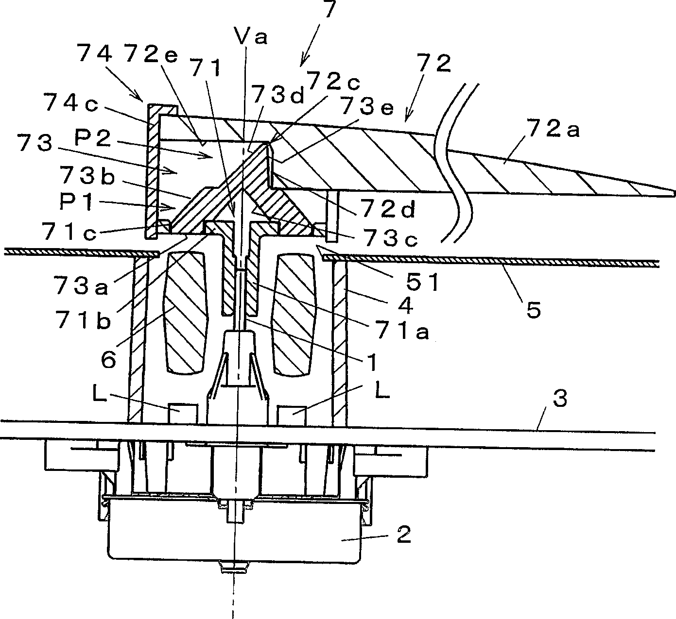
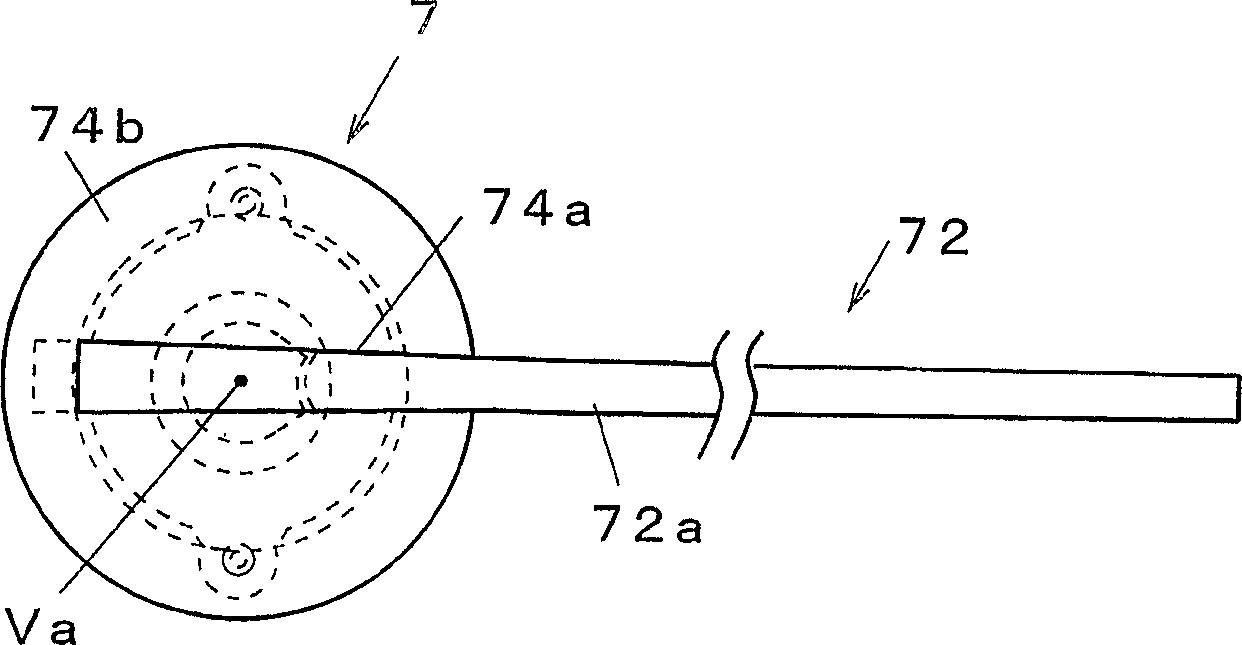
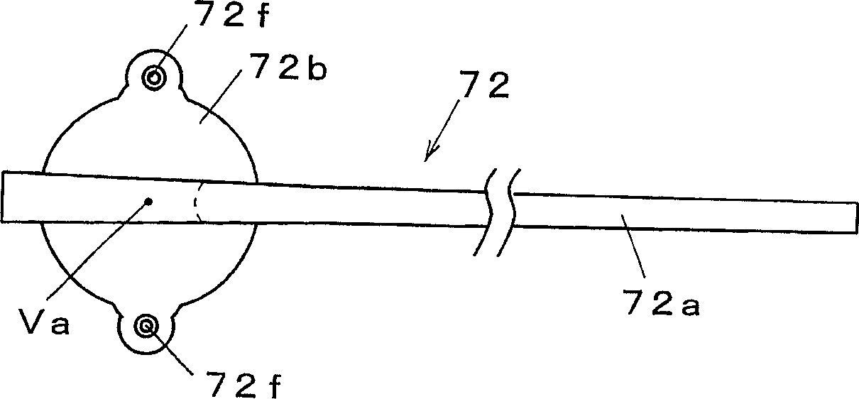
[0022] exist figure 1 Among them, the pointer instrument includes a driving device 2 protruding forward from a driving shaft 1; a circuit substrate 3 located on the front side of the driving device 2; a cylinder 4 arranged on the front side of the circuit substrate 3; The display plate 5 supported by the cylinder body 4; the light guide member 6 arranged inside the cylinder body 4; the pointer 7, which is located on the display plate 5 and rotates around the axis through the drive shaft 1 of the drive device 2; The light source L is located at the back of the display panel 5 and is installed inside the cylindrical body 4 .

[0023] The driver 2 is composed of a well-known coil motor such as a stepping motor gauge or a hollow gauge, and the drive shaft 1 is mounted on the back surface of the circuit substrate 3 so as to penetrate the circuit subs...


PUM


Abstract

A pointer lighting device which can improve a light introduction efficiency to an indicating unit, and is bright and small in lighting non-uniformity, and which comprises a pointer (7) having a translucent indicating member (indicating unit) (72) and a light introducing member (light introduction unit) (73), and being operated around and by the drive shaft (1) of a drive device (2), and a light source (L) disposed around the drive shaft (1), for allowing the indicating member (72) to emit light via the light introducing member (73), wherein the light introducing member (73) has a light receiving surface (73a) for receiving a light from the light source (L), a first reflection surface (73b) for condensing a light introduced from the light receiving surface (73a) toward the rotation axis (Va) position of the drive shaft (1), a second reflection surface (73c) formed between this first reflection surface (73b) and the rotation axis, for reflecting a light from the first reflection surface (73b) in a direction along the rotation axis (Va), and a third reflection surface (73d) formed on the rotation axis (Va) so as to face the second reflection surface (73c), for reflecting a light from the second reflection surface (73c) in the longitudinal direction of the indicating member (72).

Description

technical field [0001] The present invention relates to a pointer illuminating device which is used in a pointer instrument such as a vehicle, and which illuminates a pointer moved by a drive shaft of a predetermined driving device. Background technique [0002] Conventionally, as such a pointer lighting device, for example, a type described in JP-A-8-043145 is known. The pointer lighting device described in this document includes a pointer made of a light-transmitting material that moves around an axis together with a drive shaft; a plurality of light sources that make the pointer emit light, and a light introduction portion that introduces light from the light source is formed on the pointer, In addition, the light source is arranged in a circular shape centering on the drive shaft on the moving track of the light introducing part. In addition, the light introducing part moves sequentially on each light source arranged in a circle, thereby introducing the light of the lig...

Claims


Application Information

Patent Timeline
Patent Type & Authority Applications(China)
IPC IPC(8): G01D11/28G01D13/28G12B11/04B60K35/00F21V8/00G01D13/22G01D13/26
CPCG12B11/04G01D13/28G02B6/0018G01D11/28G02B6/0028G01D13/265B60K2360/6992B60K35/00
Inventor 正司直路小幡雅人
Owner NIPPON SEIKI CO LTD
Learn More