Antenna comprising a plastic housing

An antenna and plastic technology, applied in the field of automotive antennas, can solve problems such as the influence of antenna functions

Inactive Publication Date: 2006-04-12
HIRSCHMANN ELECTRONICS GMBH & CO KG
View PDF1 Cites 2 Cited by
  • Summary
  • Abstract
  • Description
  • Claims
  • Application Information

AI Technical Summary

Problems solved by technology

This means that dirt particles and mainly moisture can penetrate into the antenna housing, which can lead to an impairment of the antenna function
Also disadvantageous is the assembly and the associated component variety, since firstly the base must be provided with cutouts, and accordingly the antenna housing must have screw connections

Method used


Image

  • Antenna comprising a plastic housing

Examples


Embodiment Construction

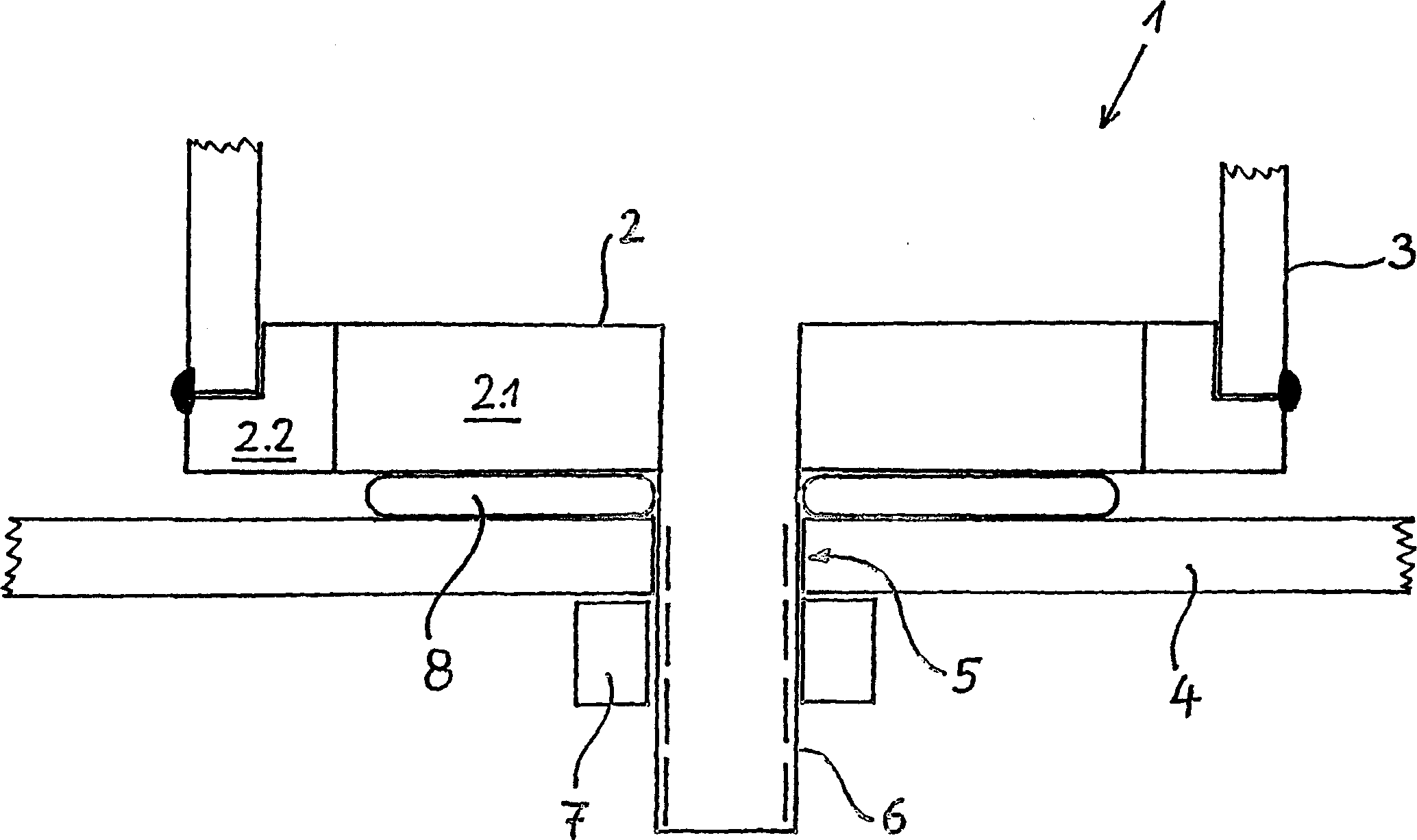
[0009] The schematically shown antenna 1 has a base body 2 , wherein the base body 2 has a metal subregion 2 . 1 which is required for the function of the antenna 1 . According to the invention, it is proposed that the base body 2 also has at least one subregion 2.2 made of plastic, which surrounds the edge of the subregion 2.1 made of metal in the present exemplary embodiment. It is conceivable here for the subregion 2 . 2 , for example made of plastic, to extend at least partially planarly above the subregion 2 . 1 made of metal. Arranged above said base body 2 is a housing 3 made of plastic, which surrounds and protects antenna elements (including in some cases electronic components, such as amplifiers), which are arranged on base body 2 . The antenna element differs depending on the purpose of use of the antenna 1, and is not shown in the figure for the sake of simplicity. In order to seal the interior in housing 3 , housing 3 and adjacent regions of subregion 2 . 2 of ba...


PUM


Abstract

The invention relates to a vehicle antenna (1), designed to be mounted on a vehicle surface (4). Said antenna comprises a base body (2) consisting of metal and a plastic antenna housing (3), which surrounds the antenna elements that are placed on the base body (2). According to the invention, the base body (2) has at least one sub-section (2.2) consisting of plastic and the antenna housing (3) is permanently connected to said sub-section (2.2) once the antenna elements have been mounted.

Description

technical field [0001] The invention relates to a vehicle antenna for mounting on a vehicle surface, in particular a vehicle roof, having the features stated in the preamble of claim 1 . Background technique [0002] One such vehicle antenna is known from DE29500961U1. Such antennas have a base (basic body) made of metal, on which the required antenna elements (for example strip conductor antennas) are arranged. In order to protect the antenna elements arranged on the base, they are surrounded by an antenna housing made of a non-conductive material, such as plastic. The entire antenna is fixed to the surface of the vehicle by means of a bolt on the base which engages in a hole in the surface of the vehicle. [0003] The base of the antenna described in DE29500961U1 fits into a receiving opening on the bottom surface of the antenna housing, and in order to fix the antenna housing on the base, four openings are provided in the corners of the base. Thread the bolts through t...

Claims


Application Information

Patent Timeline
Patent Type & Authority Applications(China)
IPC IPC(8): H01Q1/12H01Q1/32H01Q1/42
CPCH01Q1/1214H01Q1/42H01Q1/3275
Inventor 乔奇姆·科达斯冈特·布里克尔波力斯·维施尼奥斯基
Owner HIRSCHMANN ELECTRONICS GMBH & CO KG
Why Eureka
Try Eureka