

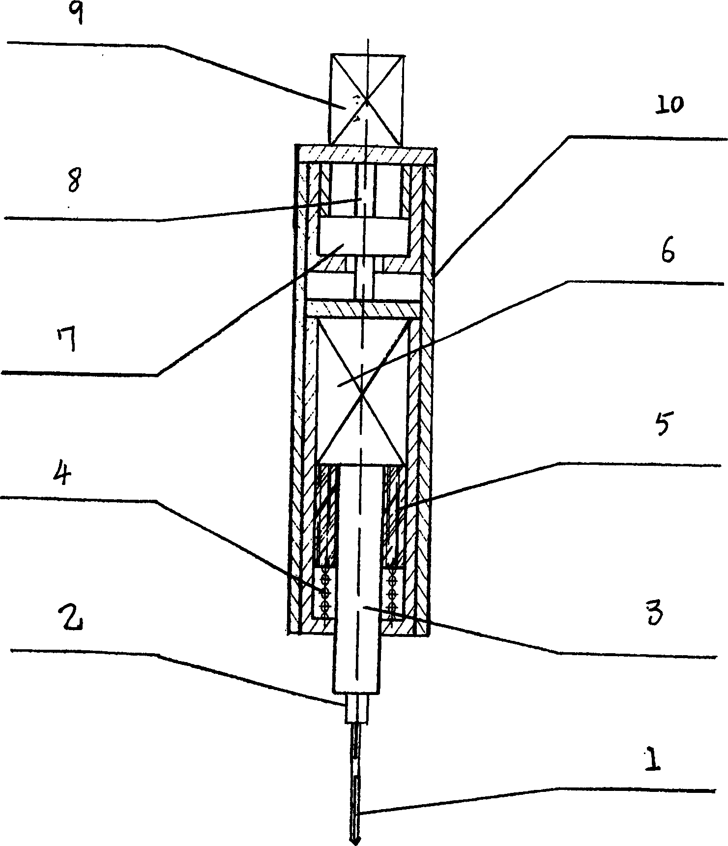
Boring machine and drilling method
A drilling method and technology of drilling machines, which are applied in drilling/drilling equipment, boring/drilling, components of boring machines/drilling machines, etc., can solve the problem that the hole accuracy and surface roughness cannot be guaranteed, and the design is difficult to achieve. requirements, extension of non-processing time, etc., to achieve the effect of reducing temperature, shortening processing time, and suppressing the decline of strength and hardness
- Summary
- Abstract
- Description
- Claims
- Application Information
AI Technical Summary
Problems solved by technology
Method used
Image


Examples
example 1
[0097] Processing example 1: processing diagram see Figure 23 , Figure 24
[0098] Part number: S10.55.041 Part material: 9Cr18
[0099] Material hardness: HB≤269 (GJB2294-95)
[0100] Process: 45, 50, 55, 60 processes
[0101] Tooling: self-made test tooling
[0102] Number of processed pieces: 12 pieces
[0103] Drill bit: Nanchang Carbide Factory production specifications φ0.45mm, φ0.60mm
[0104] Selection of processing parameters:
[0105] Spindle speed: 6000r / min; vibration frequency: 300Hz; feed rate: 3μm / r.
[0106] Program setting: initial height 20mm
[0107] G01 +1.5
[0108] G02-2
[0109] G03 +2.5
[0110] G04 -2.5
[0111] G05 +3
[0112] G06-3
[0113] G07 +3.5
[0114] G08 -3.5
[0115] G09 +4.0
[0116] G010 -4.0
[0117] G011 +4.5
[0118] G012 -4.5
[0119] G013 +5
[0120] G014-5
[0121] ...
example 2
[0128] Processing example 2: Part number: 5C12008; Part material: GH1140; Process: 15, 20; Number of processed pieces: 10 pieces
[0129] Drill bit: Nanchang Cemented Carbide Factory production specification φ0.6mm
[0130] Processing diagram see Figure 25
[0131] Selection of processing parameters:
[0132] Spindle speed: 6000r / min; Vibration frequency: 300Hz; Feed rate: 3μm / r
[0133] Program setting: initial height 12.5mm
[0134] G01 +2
[0135] G02-0000
[0136] Cooling and lubrication method: 20 # Manual oil injection
[0137] Test results: see Table 6
[0138]
serial number
Specimen
No
process
Drill Specifications
flow test
data
(cm 3 / s)
Test Description
1
1
15
0.6(1)
16.2
2
2
15
0.6(1)
16.25
3
3...
PUM
| Property | Measurement | Unit |
|---|---|---|
| Diameter | aaaaa | aaaaa |
Abstract
Description
Claims
Application Information