In-mold forming apparatus, in-mold forming method, in-mold formed article manufacturing method, and dust collector

An internal forming and cavity technology, applied in chemical instruments and methods, cleaning methods and utensils, transportation and packaging, etc., can solve the problems of increased manufacturing costs, low yield, and continuous manufacturing of defective objects, and achieve efficient accumulation. , the effect of preventing defective objects

Inactive Publication Date: 2006-04-26
KK TOSHIBA
View PDF3 Cites 3 Cited by
  • Summary
  • Abstract
  • Description
  • Claims
  • Application Information

AI Technical Summary

Problems solved by technology

In addition, when no dents are found and the foil dust P is not wiped off, there is a danger of continuous manufacturing of defective items.
[0012] Particularly, in a sub-liquid crystal panel of a cellular phone or the like, parts are transparent, and therefore the failure rate due to dents is high, and the yield of some parts is low, such as 50%-60%, and resulting in an increase in manufacturing costs

Method used


Image

  • In-mold forming apparatus, in-mold forming method, in-mold formed article manufacturing method, and dust collector
  • In-mold forming apparatus, in-mold forming method, in-mold formed article manufacturing method, and dust collector
  • In-mold forming apparatus, in-mold forming method, in-mold formed article manufacturing method, and dust collector

Examples


no. 1 example

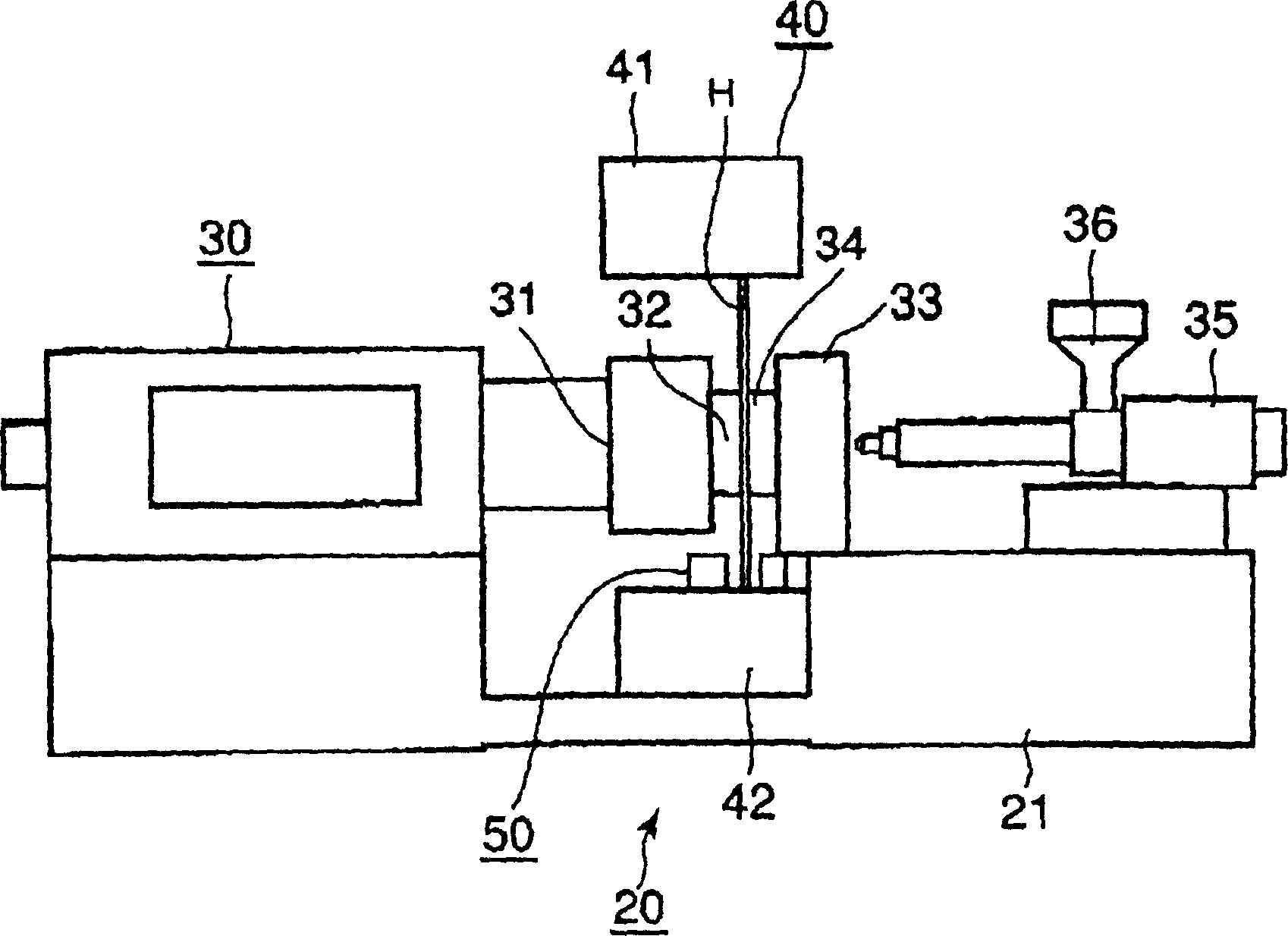
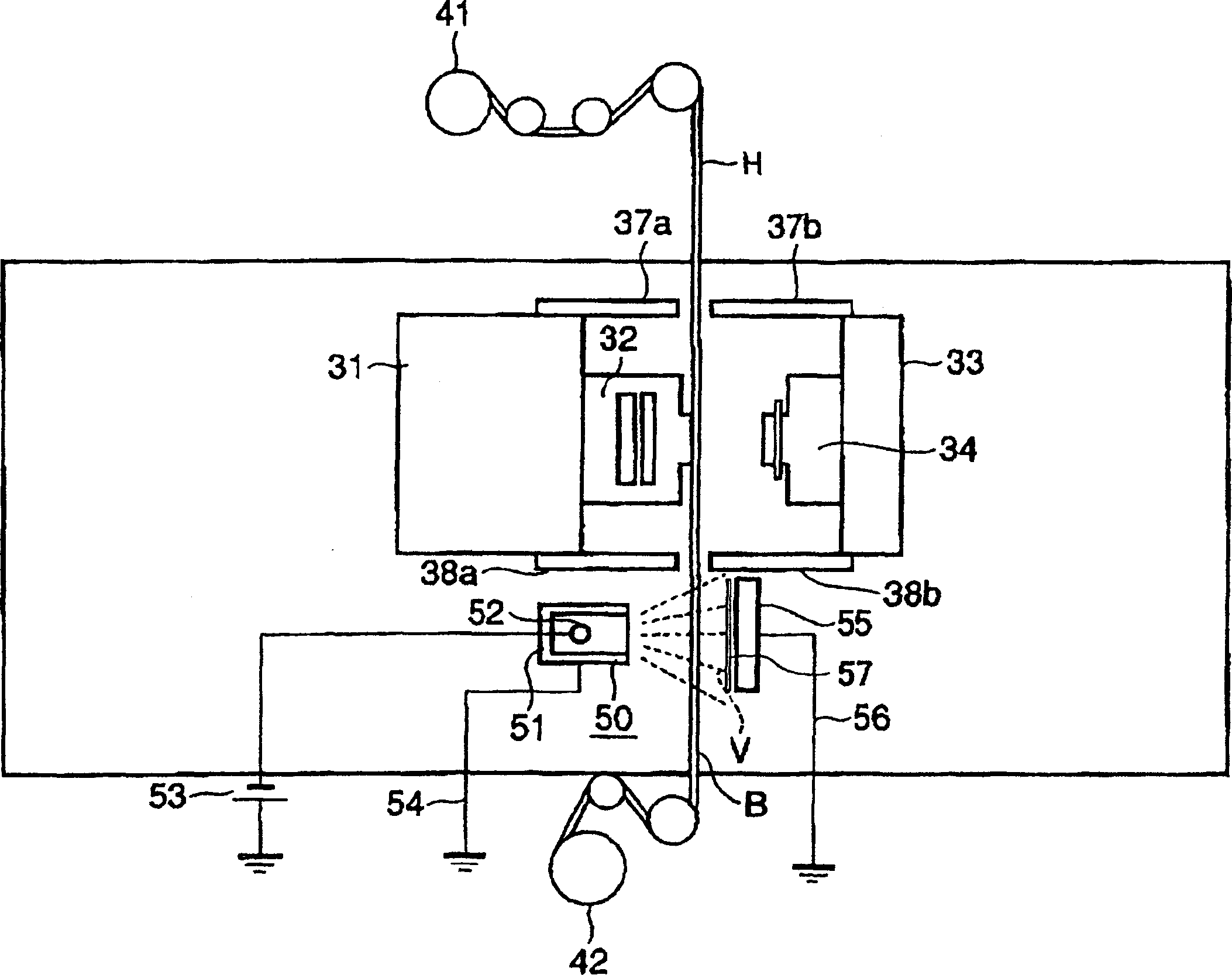
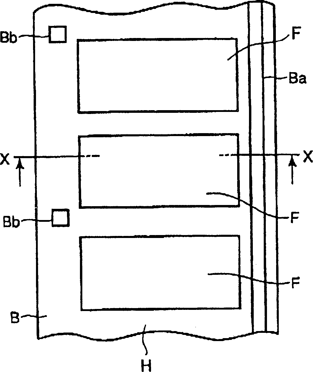
[0039] figure 1 is a front view showing the in-mold forming device 20 according to the first embodiment of the present invention, figure 2 is a schematic diagram showing the main parts of the in-mold forming device 20; image 3 is a front view showing the in-mold foil H used in the in-mold forming device 20; Figure 4 and Figure 5 is along image 3 A cross-sectional view of an example of the inner foil H cut along the middle section line X-X and viewed from the direction of the arrow; Figure 6 yes means figure 1 An illustration of the principle of operation of the in-mold forming device 20 shown; Figure 7 to Figure 9 are cross-sectional views each showing the injection molding step of the in-mold forming device 20; in addition, in these drawings, the numeral H denotes an in-mold foil, B denotes a base film, F denotes a transfer foil, and P denotes foil dust.

[0040] Such as figure 1 As shown, the in-mold forming device 20 is provided with: a frame 21 loaded on t...

no. 2 example

[0055] Figure 10 It is a perspective view schematically showing an in-mold forming device 60 according to a second embodiment of the present invention. exist Figure 10 use the same notation in the figure 2 The same functional parts shown in , and its detailed description is omitted.

[0056] In the aforementioned in-mold forming apparatus 20 of the first embodiment, the charger 50 is installed only on the foil winder side viewed from the cavity side mold 32 and the core side mold 34 . However, in the in-mold forming apparatus 60 of the present embodiment, the charger 50 is additionally installed on the foil feeder 41 side as well as on the cavity side mold 32 and the core side mold 34 . In addition, the charging body 51 and the plate electrode 55 are mounted at symmetrical positions with respect to the in-mold foil H. As shown in FIG.

[0057] Also in the in-mold forming device 60 thus constituted, the same effects as those possessed by the above-mentioned in-mold formi...

no. 3 example

[0059] Figure 11 It is a perspective view schematically showing an in-mold forming device 70 according to a third embodiment of the present invention. exist Figure 11 use the same notation in the figure 2 The same functional parts shown in , and its detailed description is omitted.

[0060] In the aforementioned in-mold forming device 20 of the first embodiment and the in-mold forming device 60 of the second embodiment, the in-mold foil feeding mechanism 40 is installed only in the vertical direction. However, in the in-mold forming device 70 of the present embodiment, the in-mold foil feeding mechanisms 40 are arranged one after the other in the vertical direction and the horizontal direction. Therefore, the in-mold forming device 70 can realize composite in-mold forming in which the in-mold foils H are arranged in the vertical direction and the horizontal direction.

[0061] In addition, chargers 50 are respectively installed on the respective sides of the foil feeder...


PUM


Abstract

An in-mold forming device includes: a first mold and a second mold for injection molding, and a film feeding mechanism for supplying an in-mold foil between the first mold and the second mold. A transfer foil is formed on the in-mold foil. The in-mold forming device also includes: a mold closing mechanism for closing the first mold and the second mold, thereby fixing the in-mould foil in the cavity formed between the first mold and the second mold; a resin injection molding mechanism for injecting resin into the cavity, thereby integrating the transfer foil formed on the in-mold foil with the resin; device. The charger includes a charging unit for releasing ions and charging the particles in the adjacent area of ​​the inner foil, and electrodes for absorbing the particles charged by the ions.

Description

[0001] Cross References to Related Applications [0002] This application is based upon and claims the benefit of priority from prior Japanese Patent Application No. 2004-306161 filed on October 20, 2004, the entire contents of which are incorporated herein by reference. technical field [0003] The present invention relates to an in-mold forming device, an in-mold forming method, and a manufacturing method of an in-mold formed part, and more particularly relates to an in-mold forming device, an in-mold forming method, and a method for use in portable phones, mobile information terminal devices, notebook personal computers, household appliances, automobile components, etc. In-mold forming device, in-mold forming method and in-mold forming part manufacturing method. In addition, the present invention relates to a dust collector, more particularly to a dust collector capable of efficiently accumulating dust. Background technique [0004] Conventionally, by using an in-mold fo...

Claims


Application Information

Patent Timeline
Patent Type & Authority Applications(China)
IPC IPC(8): B29C45/14B03C3/00B29C45/17B65H20/00
CPCB03C3/017B08B6/00B29C45/14016B29C45/14827B29C45/1701
Inventor 海陆嘉德小池昇
Owner KK TOSHIBA
Why Eureka
Try Eureka