Polarization light emitting apparatus for light orientation

An irradiation device and a technology of light irradiation, applied in polarizing elements, optics, nonlinear optics, etc., can solve problems such as difficult to use and complicated processes

Active Publication Date: 2006-05-10
USHIO DENKI KK
View PDF4 Cites 27 Cited by
  • Summary
  • Abstract
  • Description
  • Claims
  • Application Information

AI Technical Summary

Problems solved by technology

[0037] Therefore, when irradiating polarized light having an oblique direction of the polarization axis, it is necessary to obtain the grid direction for obtaining the desired polarization axis direction through preliminary experiments or calculations, and the process becomes very complicated.
[0038] Therefore, in the method of changing the grid direction of the wire grid polarizing element with respect to the longitudinal direction of the lamp, although it can be used in producing an orientation direction parallel to the conveyance direction or an orientation direction orthogonal to the orientation film; but in addition , which is difficult to use in orientations that yield oblique orientations

Method used


Image

  • Polarization light emitting apparatus for light orientation
  • Polarization light emitting apparatus for light orientation
  • Polarization light emitting apparatus for light orientation

Examples


Embodiment Construction

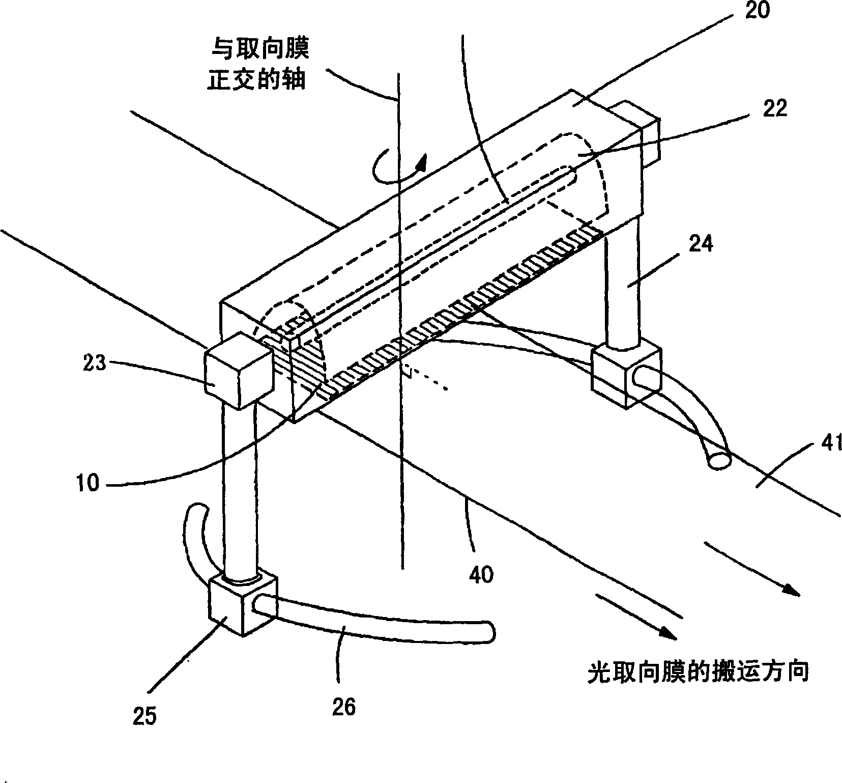
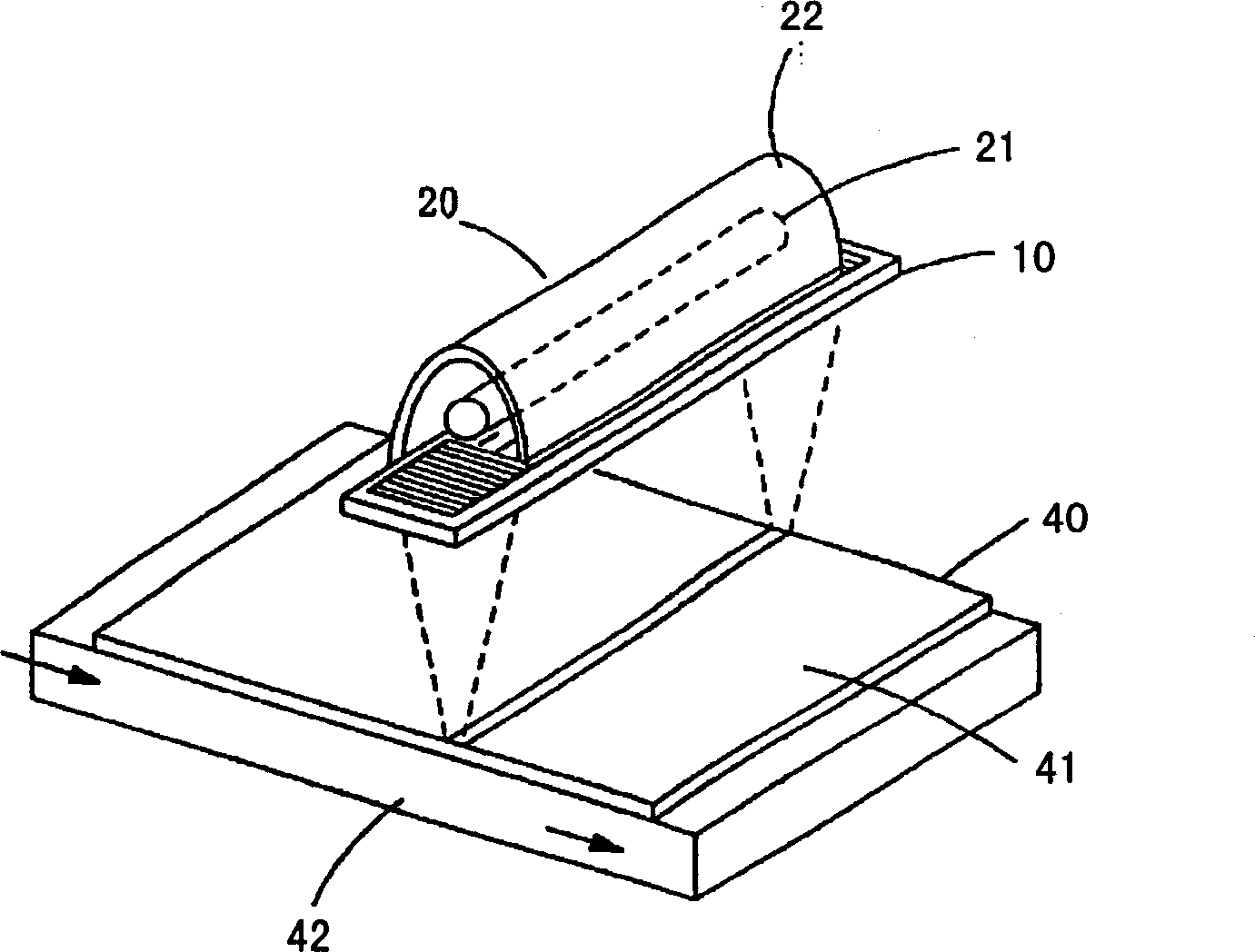
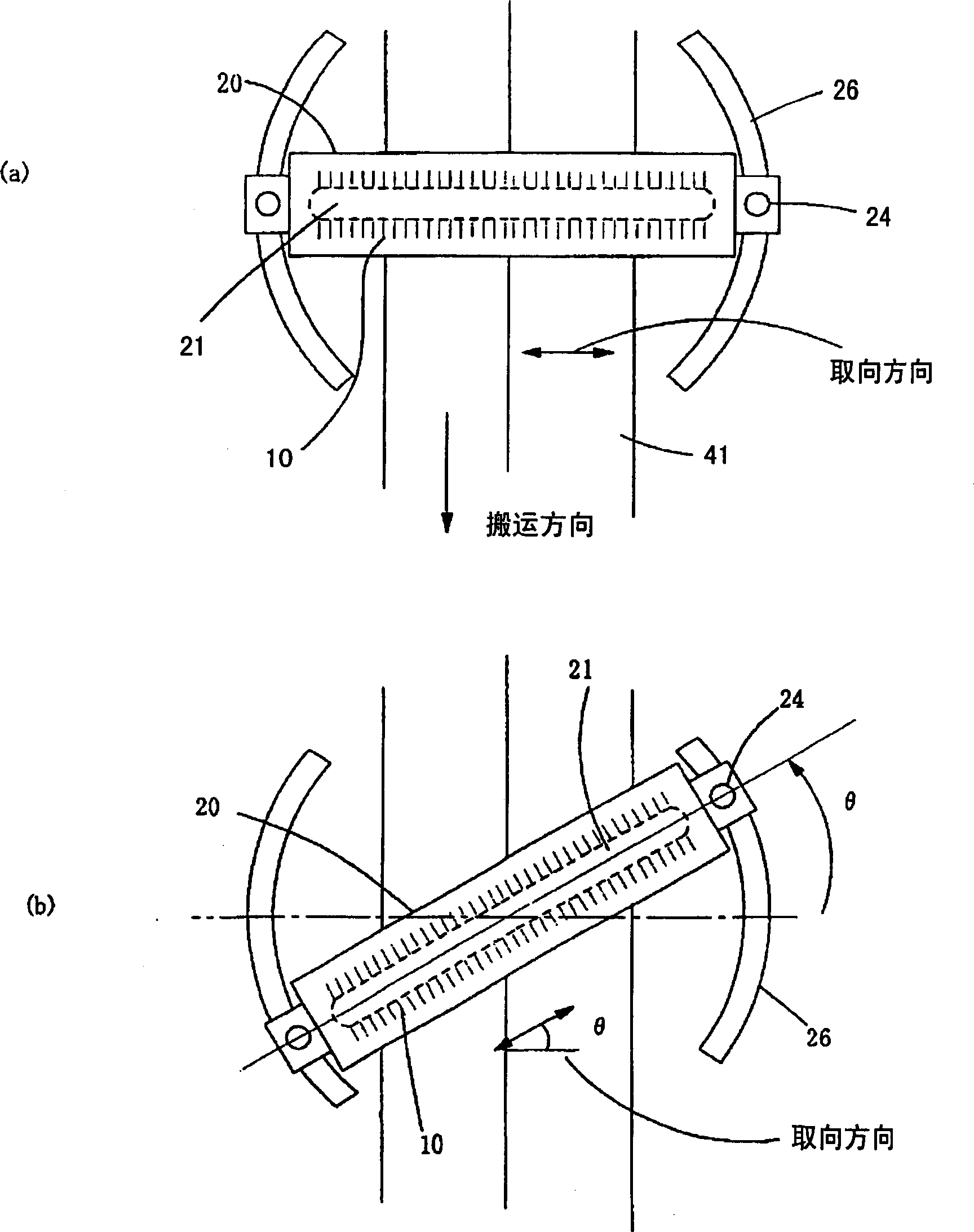
[0064] figure 1 It is a figure which shows the structure of the polarized-light irradiation apparatus of the Example of this invention.

[0065] Such as figure 1 shown, with Figure 15 A rod-shaped lamp 21 , which is also a linear light source such as a high-pressure mercury lamp or a metal halide lamp, and a sink-shaped condenser lens 22 that reflects light from the lamp 21 are incorporated in the light irradiation unit 20 . Furthermore, a wire grid polarizing element 10 is provided on the light exit side.

[0066] In addition, rod lamps are described below as linear light sources as examples, but LEDs and LDs that emit ultraviolet light have also been put into practical use in recent years, and such LEDs or LDs can be arranged in a straight line as a linear light source. In addition, in this case, the direction in which LEDs or LDs are arranged corresponds to the longitudinal direction of the lamp.

[0067] In addition, as the material of the photo-alignment film at pre...


PUM


Abstract

To provide a polarized light irradiation device for optical orientation, with which orientation in a desired direction is generated on an optical alignment layer irradiated with polarized light with little variations in the axis of polarization. An optical orientation processing is carried out by making the optical alignment layer 41 be irradiated with the polarized light from a light irradiation portion 20 equipped with a rod-shaped lamp 21 and a gutter shaped condensing mirror 22, and equipped with a wire grid polarization element 10 on the light emission side. Columns 24 to support the light irradiation portion 20 move along rails 26. The light irradiation portion 20 rotates and moves around an axis normal to the optical alignment layer to be conveyed. In order to set the optical orientation direction of the optical alignment layer 41 at an arbitrary angle, the light irradiation portion 20 is made to rotate and move around the axis normal to the optical alignment layer. Since the total light irradiation portion is made to rotate and move, the relation between a longitudinal direction of the lamp 21 and a grid direction of the polarization element 10 is not varied, and the variation of the axis of polarization is not fluctuated. Furthermore, the light irradiation portion 20 is optionally constructed so as to be tilted for the purpose of making the polarized light obliquely incident on the optical alignment layer 41.

Description

technical field [0001] The present invention relates to a polarized light irradiation device for photo-aligning by irradiating polarized light to a photo-alignment film such as an alignment film of a liquid crystal display element and an alignment layer of a viewing angle compensation film using ultraviolet curable liquid crystal. Background technique [0002] In recent years, for alignment treatment of alignment films of liquid crystal panels, alignment layers of viewing angle compensation films, and the like, a technology called photo-alignment in which alignment is performed by irradiating polarized light of a specific wavelength to the alignment film has been adopted. [0003] Hereinafter, the thin film provided with the alignment film or the alignment layer which aligns by the said light is collectively called a photo-alignment film. The size of the photo-alignment film increases with the increase in the size of the liquid crystal panel, and the size of the polarized li...

Claims


Application Information

Patent Timeline
Patent Type & Authority Applications(China)
IPC IPC(8): G02F1/1337
CPCG02B5/30G02F1/1303G02F1/133788
Inventor 盐谷纱由
Owner USHIO DENKI KK
Why Eureka
Try Eureka