Top plate setting structure of drum washer

A drum washing machine and top plate technology, which is applied to other washing machines, washing devices, textiles and papermaking, etc., and can solve the problems of complex top plate 30 installation operations, increased operating procedures, and reduced product production efficiency, etc.

Inactive Publication Date: 2006-05-31
LG ELECTRONICS (TIANJIN) APPLIANCES CO LTD
View PDF0 Cites 3 Cited by
  • Summary
  • Abstract
  • Description
  • Claims
  • Application Information

AI Technical Summary

Problems solved by technology

[0013] However, in the top plate setting structure of the drum washing machine designed in the prior art, several fixing brackets 42 are respectively arranged on the upper end of the control panel frame 40 by using the mounting bolts 46, so that the fixing brackets 42 and the fixing holes 32 are combined, thus the top plate 30 is set. At the upper end of the casing 2 and the control panel 14, therefore, in the installation process in this way, several fixed brackets 42 are installed on the control panel frame 40 by mounting bolts 46.
[0014] As a result, the setting operation of the top plate 30 is relatively complicated, and the operation process is correspondingly increased, which reduces the production efficiency of the product.

Method used


Image

  • Top plate setting structure of drum washer
  • Top plate setting structure of drum washer
  • Top plate setting structure of drum washer

Examples


Embodiment Construction

[0031] Hereinafter, embodiments of the present invention will be described with reference to the accompanying drawings.

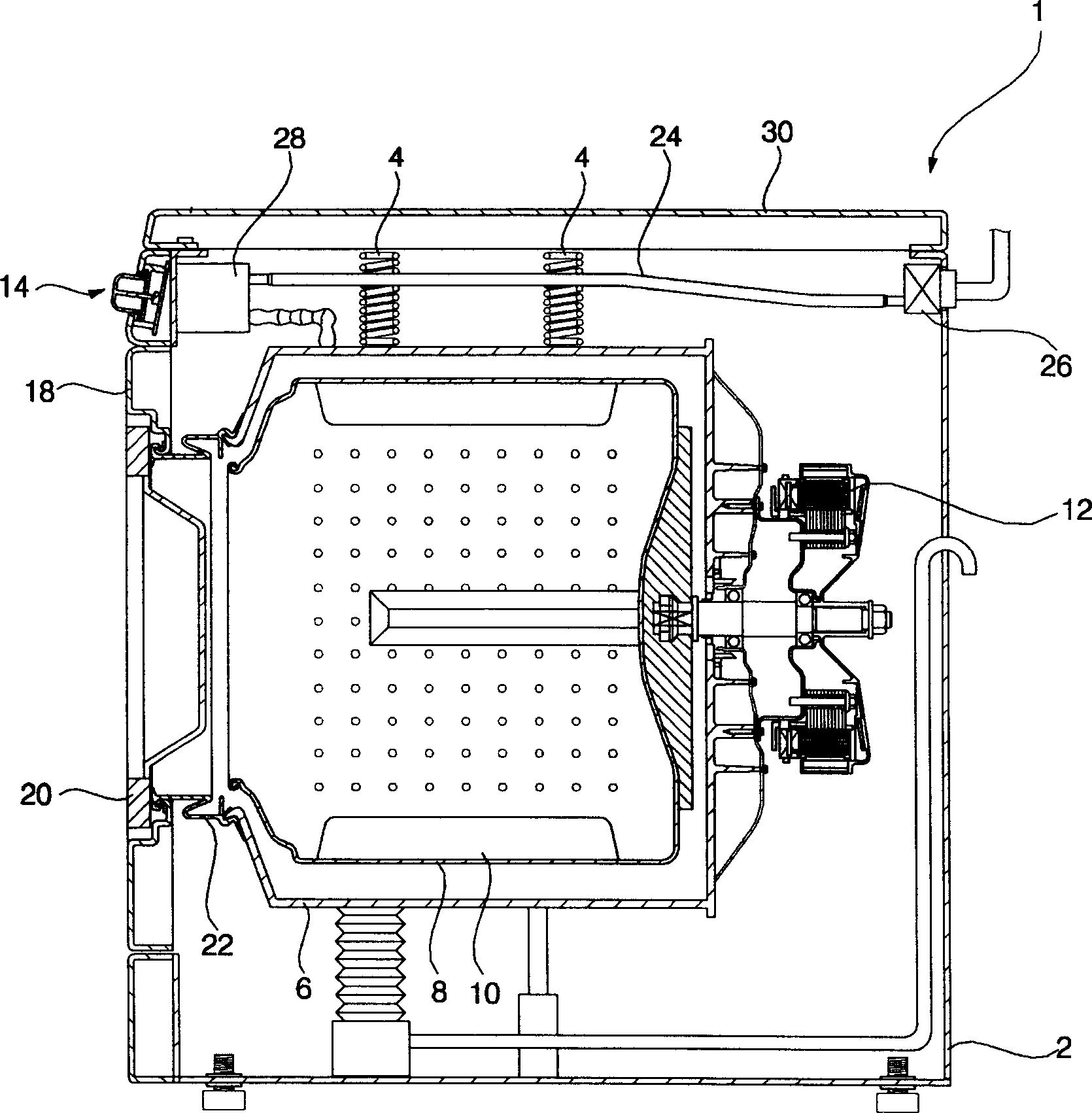
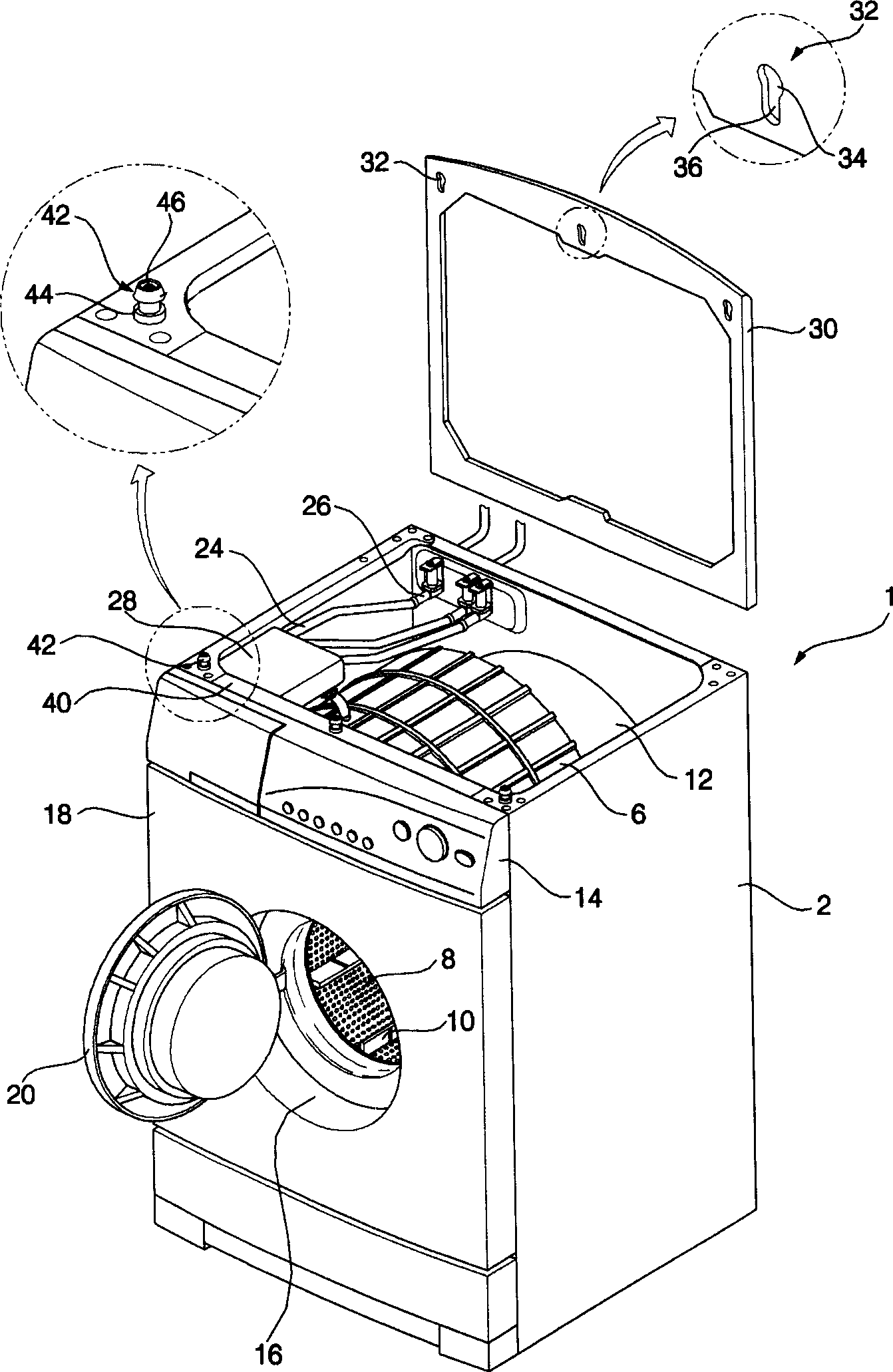
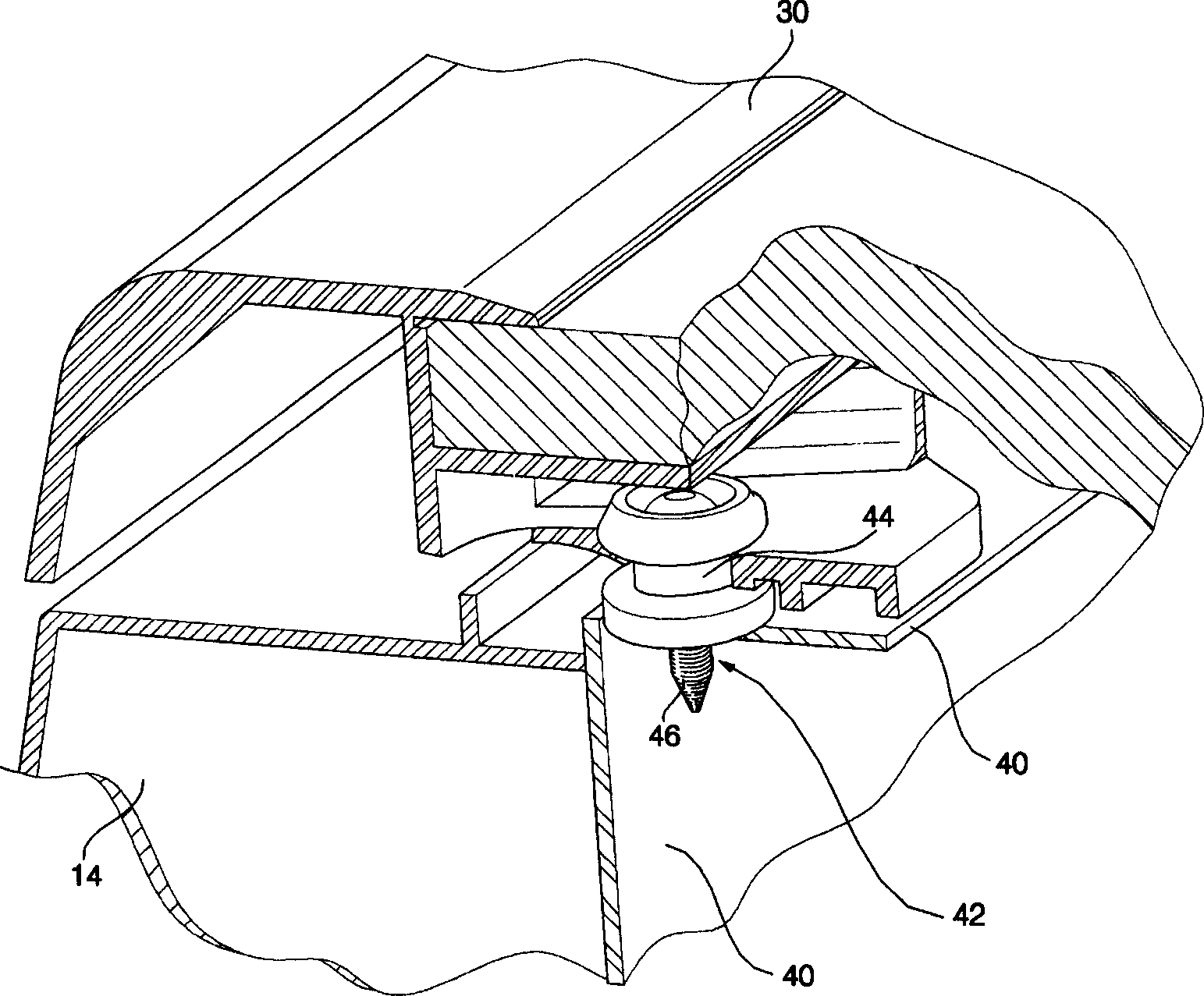
[0032] Figure 4 It is a schematic diagram of the decomposition structure of the top plate setting structure of the drum washing machine of the present invention; Figure 5 It is a structural schematic diagram of the main part of the roof setting structure of the present invention; Figure 6 It is a structural schematic diagram of the cross-section of the main part of the roof setting structure of the present invention.

[0033] Such as Figure 4 to Figure 6 As shown, the top plate setting structure of the drum washing machine designed by the present invention includes: a casing 52 that constitutes the appearance of the drum washing machine 50; it is arranged on the upper side of the front of the casing 52, and a control panel 54 with a fixed bracket 70 integrally formed thereon is arranged on it Be arranged on the top of the control panel 54 and the cas...


PUM


Abstract

The invention opens a setting structure of the head plate for rolling washer including the shell, the control panel and the fixing hole. The fixing bracket is injected in the top of the control panel, so it can set the head plate directly after installing the control panel. Because of this, it simplifies the setting process of the head plate.

Description

technical field [0001] The invention relates to a drum washing machine. In particular, it relates to a top plate installation structure of a front-loading washing machine which simplifies the installation process of the top plate and facilitates the installation work. Background technique [0002] figure 1 It is a schematic cross-sectional structure diagram of a drum washing machine in the prior art; figure 2 It is an exploded schematic view of the top plate setting structure of the drum washing machine in the prior art; image 3 It is a structural schematic diagram of the cross-section of the main part of the roof setting structure in the prior art. [0003] Such as figure 1 As shown, the drum washing machine in the prior art includes: a casing 2 that constitutes the appearance of the drum washing machine 1; an outer tub 6 that is hung inside the casing 2 by a spring 4; a drum 8 that is arranged inside the outer tub 6 for washing operations; On the inner side of the d...

Claims


Application Information

Patent Timeline
Patent Type & Authority Applications(China)
IPC IPC(8): D06F37/26
Inventor 朴种亚
Owner LG ELECTRONICS (TIANJIN) APPLIANCES CO LTD
Why Eureka
Try Eureka