
Eyeshade

An eye mask, an integrated technology, applied in the directions of eye mask, eye surgery, glasses/goggles, etc., can solve the problems of difficult to use for a long time, unable to blink, poor wearing feeling, etc., to achieve comfortable storage, improve wearability, and easy to take off Effect

Inactive Publication Date: 2006-07-05
NAWARI TRADING
View PDF0 Cites 0 Cited by
  • Summary
  • Abstract
  • Description
  • Claims
  • Application Information

AI Technical Summary

Problems solved by technology

[0004] First of all, in the case of the structure of the Japanese Patent Laid-Open No. 61-34221, since the eyeball is in direct contact with the eyeball and oppresses the eyeball, it is impossible to blink during use, resulting in eye fatigue.
[0005] In addition, in the case of the structure of the Unexamined Publication No. 61-34222, since the cold storage member is provided at the part corresponding to the eyeball, and the cold storage member is in direct contact with the eyeball, it is impossible to blink, and sleep cannot be performed.
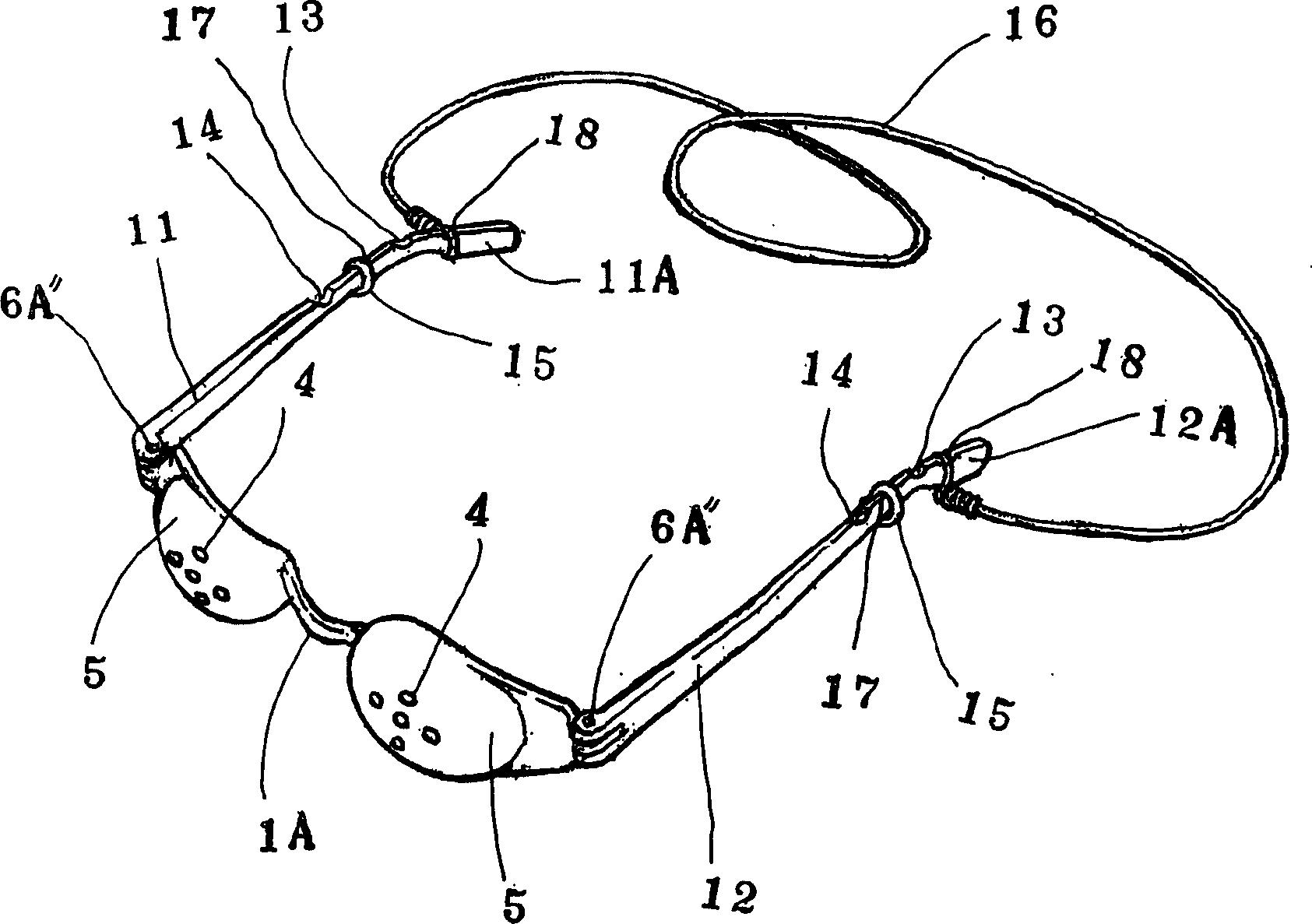
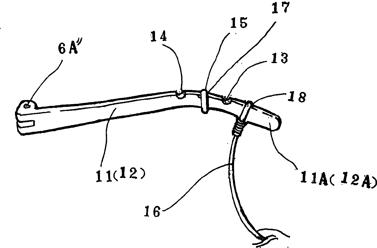
[0006] In addition, in these structures, when the eye mask is attached to the face, the strap must be hung on the ear, resulting in poor wearing feeling and difficulty in long-term use.

Method used


Image

  • Eyeshade
  • Eyeshade
  • Eyeshade

Examples


Embodiment Construction

[0022] Next, preferred embodiments of the eye mask of the present invention will be described in detail with reference to the drawings.

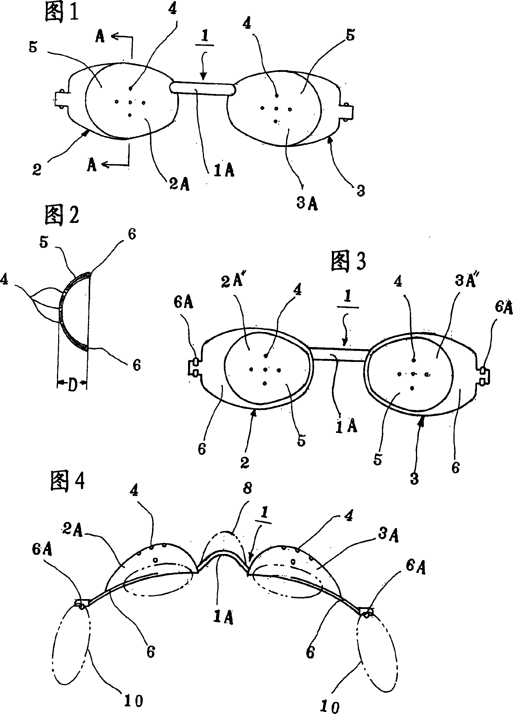
[0023] Fig. 1 to Fig. 4 are the figures that represent the eye mask of the present invention, Fig. 1 is a front view, Fig. 2 is a sectional view along line A-A of Fig. 1, Fig. 3 is a back view of Fig. 1, Fig. 2 FIG. 4 is a plan view showing the state when it is worn on the face.

[0024] In the figure, reference numeral 1 indicates a goggle having a pair of first and second goggle parts 2, 3, and each goggle part 2, 3 is integrally connected by a connection part 1A made of elastic elastic material.

[0025] Each of the above-mentioned eye mask parts 2, 3 is constituted in the following form: the overall shape has concave portions 2A", 3A" constituted by a concave shape that is concave into a substantially hemispherical shape, and the central surface of each concave portion 2A"-3A" The wall 5 is formed with a plurality of small holes 4 throu...


PUM


Abstract

An eye mask set has the first and the second concave eye masks with many pinholes on its external surface and the annular edge, and a link unit for linking the first and the second eye masks.

Description

technical field [0001] The present invention relates to an eye mask, and particularly relates to a new improvement for achieving the following two purposes: when the shape of each eye mask part is made into a concave shape and worn on the face, in order to be able to blink freely, and at the same time In particular, by providing an O-ring in the groove, the wearability of the eye mask can be reliably maintained, and a good wearing feeling can be maintained; or, by providing a strap in the groove, when the eye mask is removed from the face, it can Hanging on the neck or shoulders, it can greatly increase the convenience of wearing and taking off the eye mask, and the aforementioned grooves are arranged at the rear of each hook. Background technique [0002] In the past, various structures have been proposed and adopted for this kind of eyewear used. Among them, if the representative structure is discussed, although it is not shown in the figure, it can be cited as JP-A-61-342...

Claims


Application Information

Patent Timeline
Patent Type & Authority Applications(China)
IPC IPC(8): A61F9/04
CPCG02C7/165G02C7/16
Inventor 北山英博
Owner NAWARI TRADING
Learn More