Radio-corrected timepiece

A technology of radio and timer, applied in the field of radio calibration timer, can solve the problems of tuning frequency change, small size of rod antenna, low work efficiency and so on

Inactive Publication Date: 2006-07-12
SEIKO INSTR INC
View PDF1 Cites 8 Cited by
  • Summary
  • Abstract
  • Description
  • Claims
  • Application Information

AI Technical Summary

Problems solved by technology

[0010] In the reception sensitivity adjustment method described above, regarding the method of replacing the capacitance of the capacitor, since the adjustment is performed by combining a plurality of capacitors, the work of assembling the radio correction timer becomes troublesome, so that there is a problem of low work efficiency, which is Since it takes a long time to make the above adjustments
[0011] Also, since the rod antenna is relatively small in size and has

Method used


Image

  • Radio-corrected timepiece
  • Radio-corrected timepiece
  • Radio-corrected timepiece

Examples


Embodiment Construction

[0037] Hereinafter, a radio correction timer related to an embodiment of the present invention is explained.

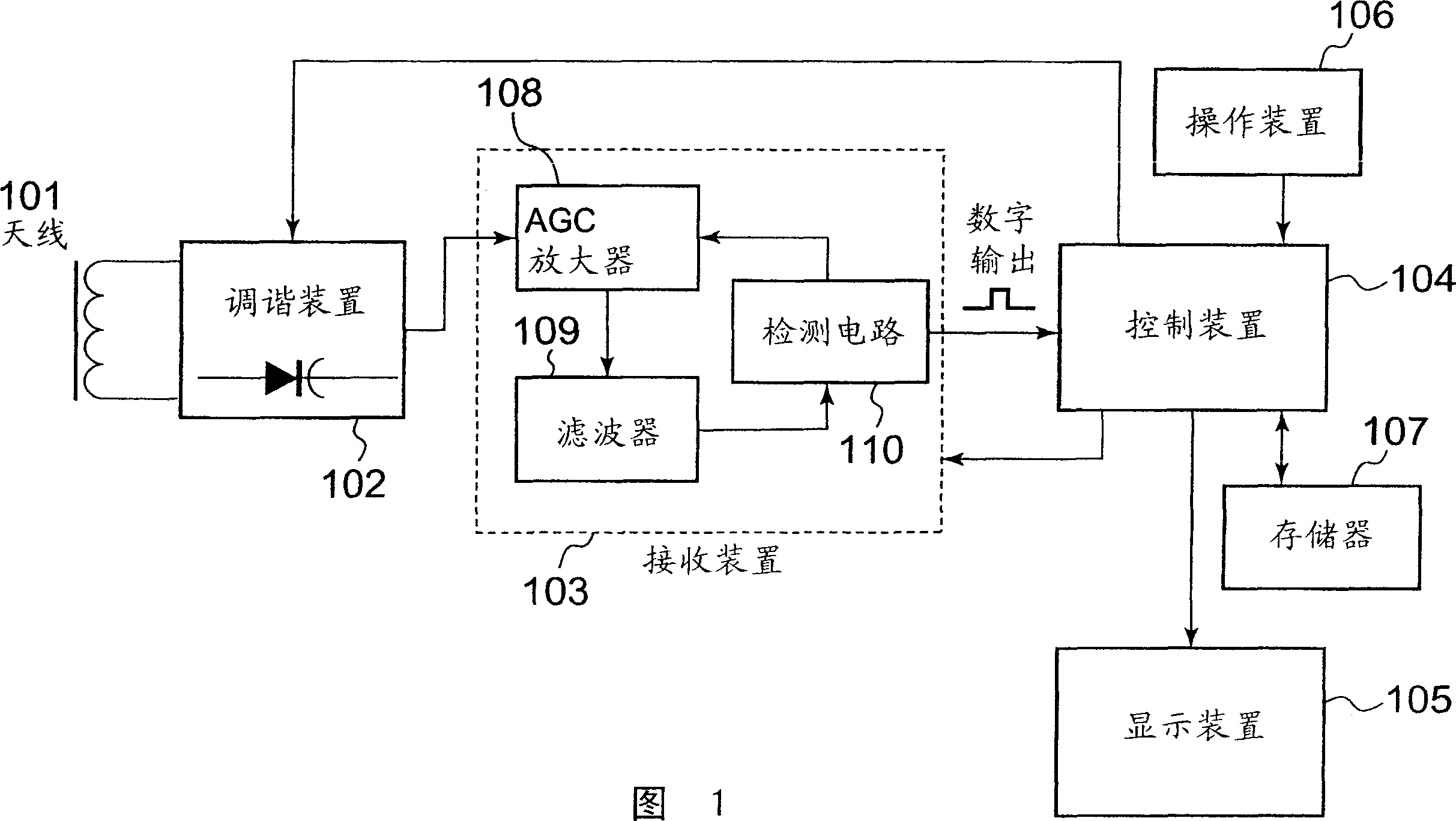
[0038] FIG. 1 is a block diagram of a radio correction timer related to an embodiment of the present invention, which is an example of a radio correction timer in which by using Figure 4 time correction using the Japanese standard wave signal shown in .

[0039] In FIG. 1, the radio correction timer has: an antenna 101 constituted by an antenna coil; a tuning device 102 having a variable capacitance diode (variable capacity) as a variable capacitance device for changing the tuning frequency; A receiving device 103; a control device 104 constituted by a central processing unit (CPU), which performs control of each constituent element and the entire radio correction timer, etc.; a display device 105 constituted by a liquid crystal display or the like, which displays the current time etc.; An operating device 106 composed of an operating switch, etc., which is used to e...


PUM


Abstract

A reception means extracts a time code from a radio signal received by an antenna, thereby outputting it to a control means. The control means obtains an information of a present time instant from the time code extracted by the reception means and corrects a present time instant being clocked by its own clock means. A display means displays the present time instant being clocked by the clock means. In a case where there has been judged that the time code is not outputted from the reception means, the control means controls so as to alter a tuning frequency by altering a capacity value of a variable capacity diode.

Description

technical field [0001] The present invention relates to a radio correcting timepiece in which time is corrected based on time information received via radio waves. Background technique [0002] For a long time, radio-corrected timepieces have been developed in which the time is automatically corrected by receiving a radio signal indicating the precise time. [0003] Currently, a long-wave standard wave on which time information is superimposed is transmitted from a radio station provided at a predetermined position in each country (for example, Germany, Japan, the United States, the United Kingdom, etc.). In Japan, the long-wave standard waves of 40kHz and 60kHz pass through similar Figure 4 The time code format of the two signals are amplitude modulated separately, and then they are sent from two transmitting stations. [0004] A radio correction timer that receives such a long-wave standard wave is commercialized, and the time data of the clock circuit is corrected in th...

Claims


Application Information

Patent Timeline
IPC IPC(8): G04G5/00G04G15/00G04R20/10
Inventor 斋藤顺孝
Owner SEIKO INSTR INC
Why Eureka
Try Eureka