

Electronic control apparatus equipped with malfuction monitor
a technology of electronic control apparatus and malfuction monitor, which is applied in the direction of electric control, instruments, digital computer details, etc., can solve the problems of fuel vapors being released into the atmosphere, difficulty in diagnosing the malfunction of the evaporative purge system correctly, and difficulty in writing the activation history record in the sram correctly
- Summary
- Abstract
- Description
- Claims
- Application Information
AI Technical Summary
Benefits of technology
Problems solved by technology
Method used
Image

Examples
first embodiment
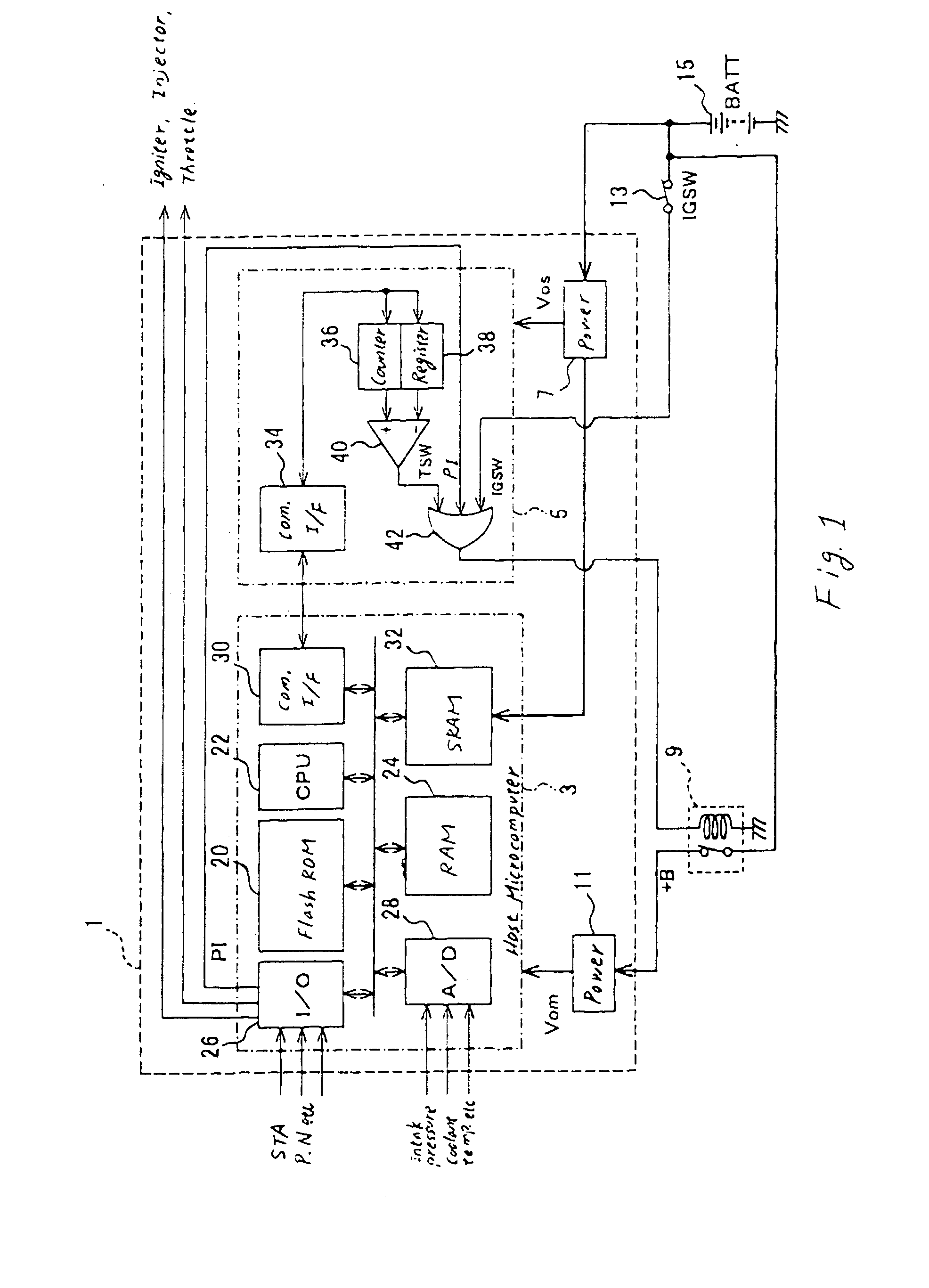
[0060] Referring to the drawings, wherein like reference numbers refer to like parts in several views, particularly to FIG. 1, there is shown an engine electronic control unit (ECU) 1 according to the invention which is mounted in an automotive vehicle.
[0061] The engine ECU 1 consists essentially of a host microcomputer 3, a timer circuit 5, and power supply circuits 7 and 11. The host microcomputer 3 works to perform arithmetic, logic, and decision-making operations to control an operating condition of an engine of the vehicle. The timer circuit 5 works to count the time elapsed since the host microcomputer 3 is deactivated following turning off of an ignition switch (IGSW) 13 of the vehicle. The power supply circuit 7 works to provide an operating voltage Vos of 5V to the timer circuit 5. The power supply circuit 11 works to provide an operating voltage Vom of 5V to the host microcomputer 3.
[0062] The power supply circuit 5 is supplied with a battery voltage VB at all times from ...
second embodiment
[0101]FIG. 6 shows the engine ECU 1 according to the invention.
[0102] The ECU 1 consists essentially of a microcomputer 411, a timer IC 413, a power supply circuit 415, an input circuit 423, and a main relay control circuit 425. The microcomputer 411, like the first embodiment, works to perform some tasks for controlling the engine of the vehicle. The timer IC 413 works to count the time for which the microcomputer 411 is at rest. The power supply circuit 415 is made up of a main power supply 415a, a first sub-power supply 415b, and a second sub-power supply 415c. The main power supply 415a works to provide electrical power or operating voltage Vm to turn on the microcomputer 411. The first sub-power supply 415b works to supply sub-voltage Vs1 to a SRAM 411a installed within the microcomputer 411 for retaining data therein at all times. The second sub-power supply 415c works to provide sub-voltage Vs2 to activate the timer IC 413. The operating voltage Vrm and the sub-voltage Vs2 ar...
fifth embodiment
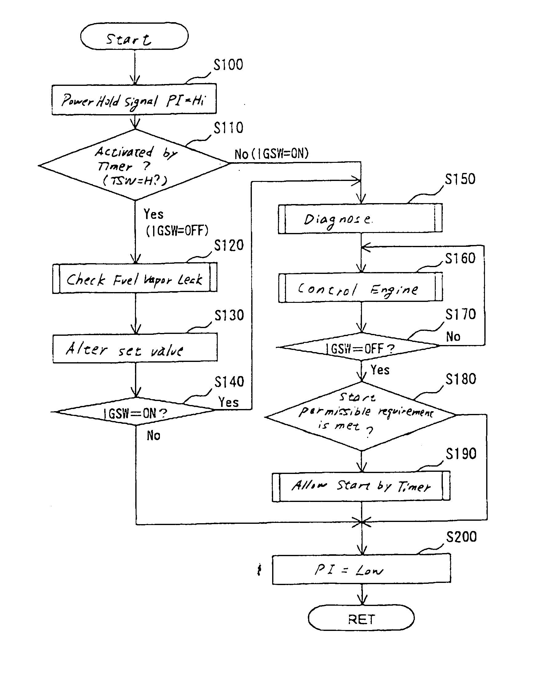
[0183]FIG. 15 shows the engine ECU 1 which is designed to diagnose an evaporative purge system 100 upon activation by a soak timer 5 during stop of the engine and also to monitor an operating state of the soak timer 5 in order to eliminate an error in the diagnosis of the evaporative purge system 100. The timer-activated history record and a count value of the soak timer 5 are saved in a nonvolatile memory, as will be describe later in detail, and used for detecting a malfunction of the soak timer 5 upon start-up of the engine.
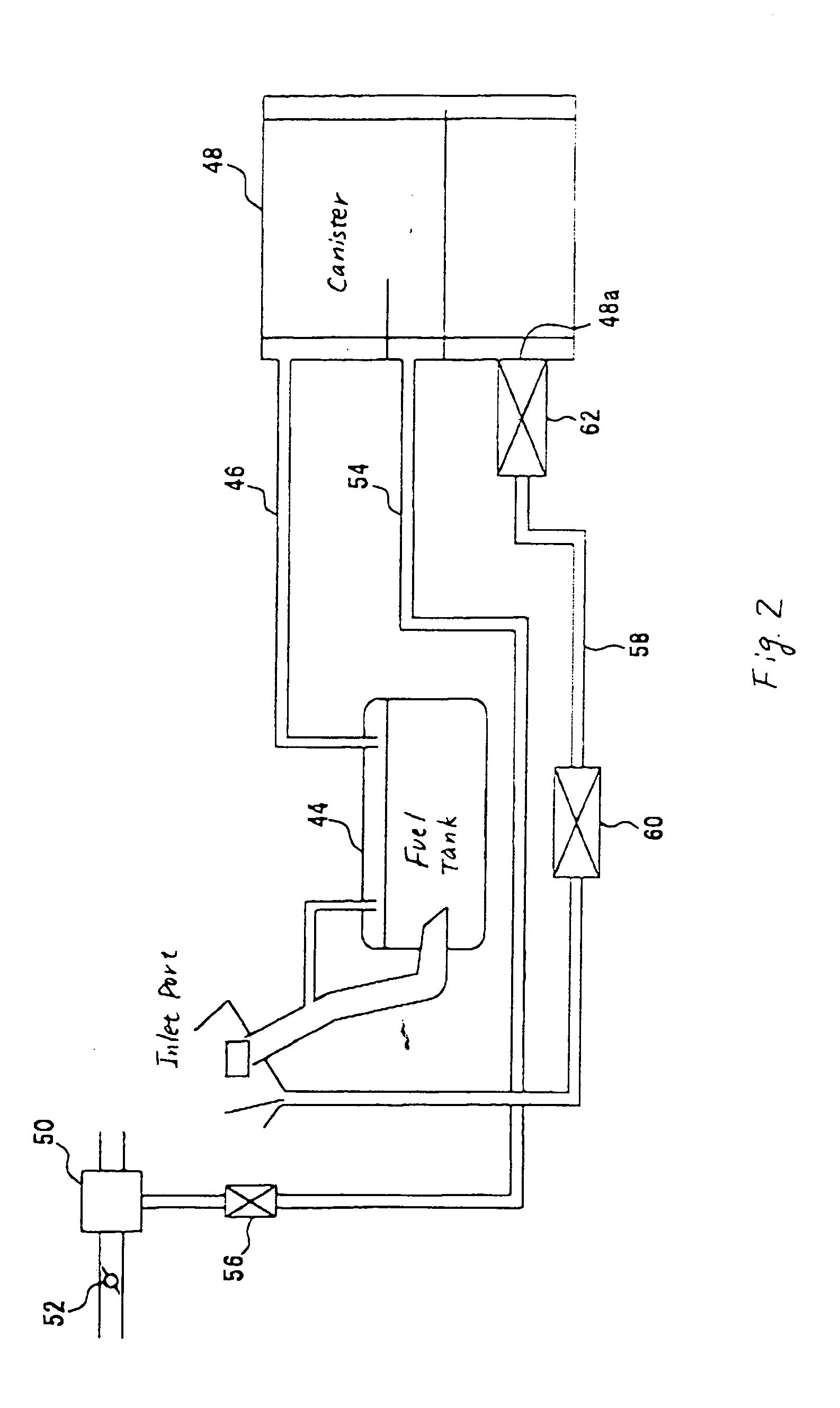
[0184] The evaporative purge system 100 works to supply fuel vapor generated within the fuel tank 44 to the engine E. The engine E is, for example, a four-cylinder gasoline engine equipped with combustion chambers 47 (only one is shown for the brevity of illustration) connecting with inlet paths 66 and exhaust paths 68. The inlet paths 66 have installed therein injectors 123.
[0185] The evaporative purge system 100 includes a canister 48, an evaporative emiss...
PUM
 Abstract
Description
Claims
Application Information