Optical switch and making method thereof

A manufacturing method and technology of optical switches, which are applied in optics, optical components, nonlinear optics, etc., can solve the problems of low light transmittance of liquid crystal optical switches, difficulty in improving the brightness of projection display equipment, etc., so as to avoid light energy from being absorbed, The effect of high light transmittance

Inactive Publication Date: 2006-07-26
HONG FU JIN PRECISION IND (SHENZHEN) CO LTD +1
View PDF3 Cites 4 Cited by
  • Summary
  • Abstract
  • Description
  • Claims
  • Application Information

AI Technical Summary

Problems solved by technology

[0008] In order to solve the problem that the light transmittance of the liquid crystal light switch is low in the prior art, which makes it difficult to improve the brightness of the projection display device, the purpose of the present invention is to provide an optical switch with a high light transmittance to obtain high brightness. projection display equipment

Method used


Image

  • Optical switch and making method thereof
  • Optical switch and making method thereof
  • Optical switch and making method thereof

Examples


Embodiment Construction

[0037] The present invention will be described in further detail below in conjunction with accompanying drawing.

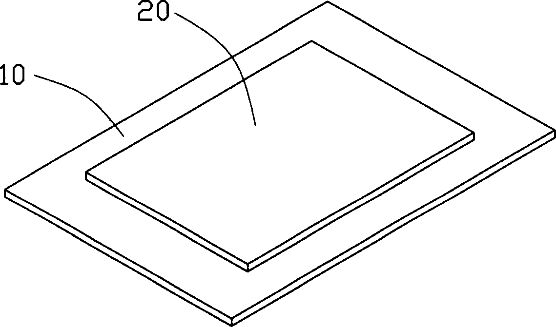
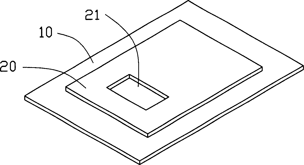
[0038] see Figure 7 , the optical switch 100 provided by the present invention, which includes: a substrate, which includes a transparent substrate 10, and a light shielding layer 20 formed on the transparent substrate 10, the light shielding layer 20 has a first through hole 21; And a comb-shaped driving structure matched with the above-mentioned substrate, which includes a first comb-shaped electrode and a second comb-shaped electrode. The first comb electrode includes a first side wall 43 , and a first top surface 41 extending from the other end of the first side wall 43 opposite to the contact end of the transparent substrate 10 . The first top surface 41 is located on the transparent substrate 10 and is substantially parallel to the transparent substrate 10. A second through hole 410 and a plurality of first interdigitated structures 411 are formed on the f...


PUM

PropertyMeasurementUnit
thicknessaaaaaaaaaa

Abstract

The invention relates to an optical switch and a method for making the same. The inventive optical switch comprises: a base with a first through hole; and comb-type driving structure which is matched with the base and includes a first comb-type electrode and a second comb electrode; wherein the first comb-type electrode includes a second through hole corresponding to the first through hole and plural first interdigital structures, and the first through hole combines the second through hole to form a light channel; the second comb-type electrode includes plural second interdigital structures for controlling the size of light channel by matching with the first interdigital structures. The invention has the advantages of being able to adjust transmitted intensity of incoming light via adjusting the size of the light channel. Also, the invention provides a method for making the optical switch.

Description

【Technical field】 [0001] The invention relates to an optical switch and a manufacturing method thereof, in particular to an optical switch applied to projection display and a manufacturing method thereof. 【Background technique】 [0002] Liquid crystal (Liquid Crystal Display, referred to as LCD) projection display technology is a digital projection display technology, which mainly uses liquid crystal optical switches as its light modulation device; Tube, referred to as CRT) projection display technology), which has the characteristics of light weight and small size. [0003] Liquid crystal projection display technology uses the photoelectric effect of liquid crystals, that is, the arrangement of liquid crystal molecules changes under the action of an electric field, which affects the light transmittance or reflectivity of the liquid crystal unit, and produces images with different gray scales and colors. [0004] See US Patent No. 4,343,535, which discloses a liquid crystal...

Claims


Application Information

Patent Timeline
Patent Type & Authority Applications(China)
IPC IPC(8): G02B26/00G02F1/1335
CPCG02F1/134309
Inventor 简扬昌
Owner HONG FU JIN PRECISION IND (SHENZHEN) CO LTD
Why Eureka
Try Eureka