

Extendable soft stent with excellent follow-up capability to blood vessel
An ability and blood vessel technology, which is applied in the field of stretchable and flexible stents with excellent follow ability to blood vessels, can solve problems such as shortening, and achieve the effects of reduced curvature deformation, good follow ability, and small damage
- Summary
- Abstract
- Description
- Claims
- Application Information
AI Technical Summary
Problems solved by technology
Method used
Image

Examples
Embodiment 1
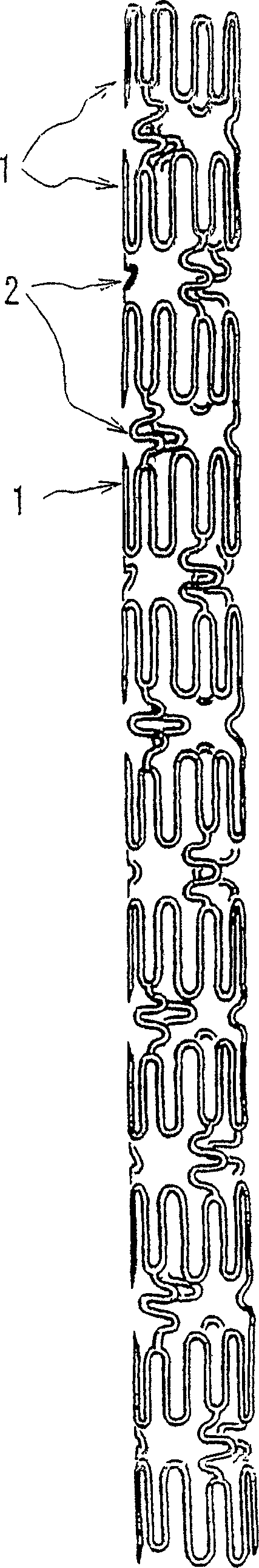
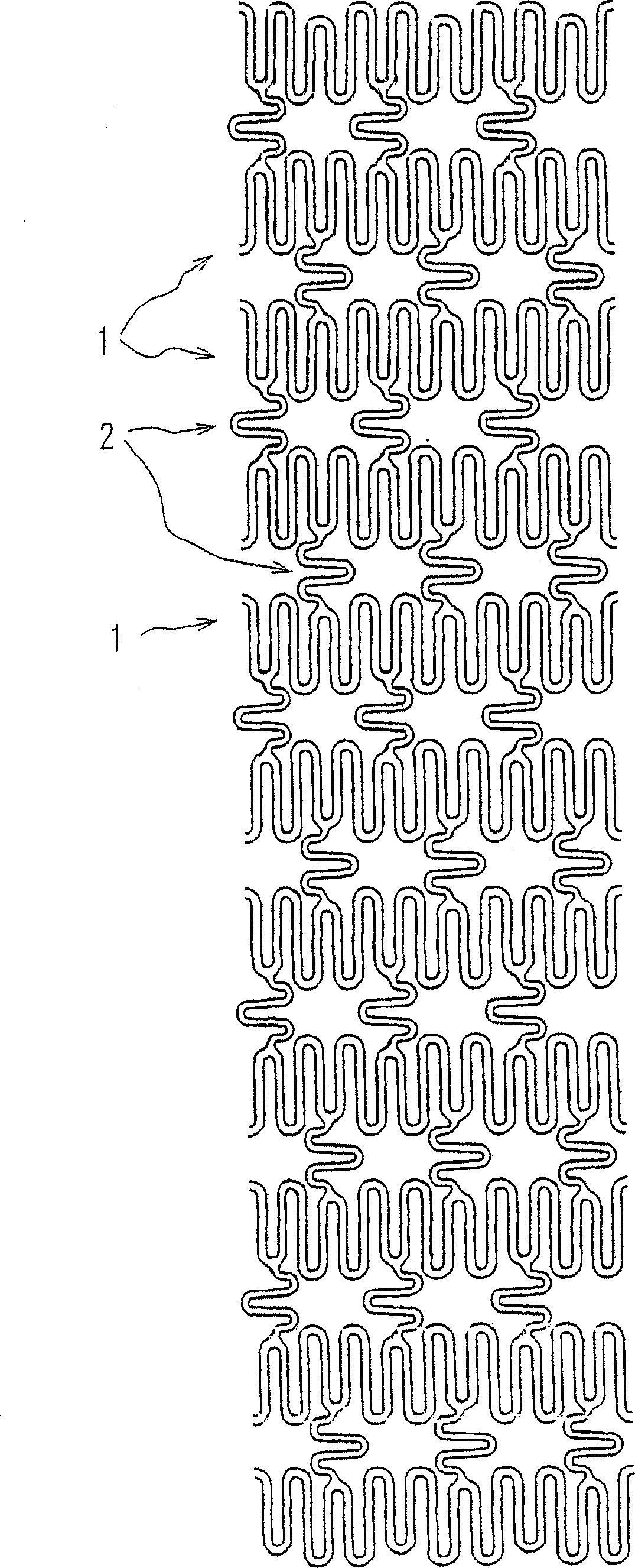
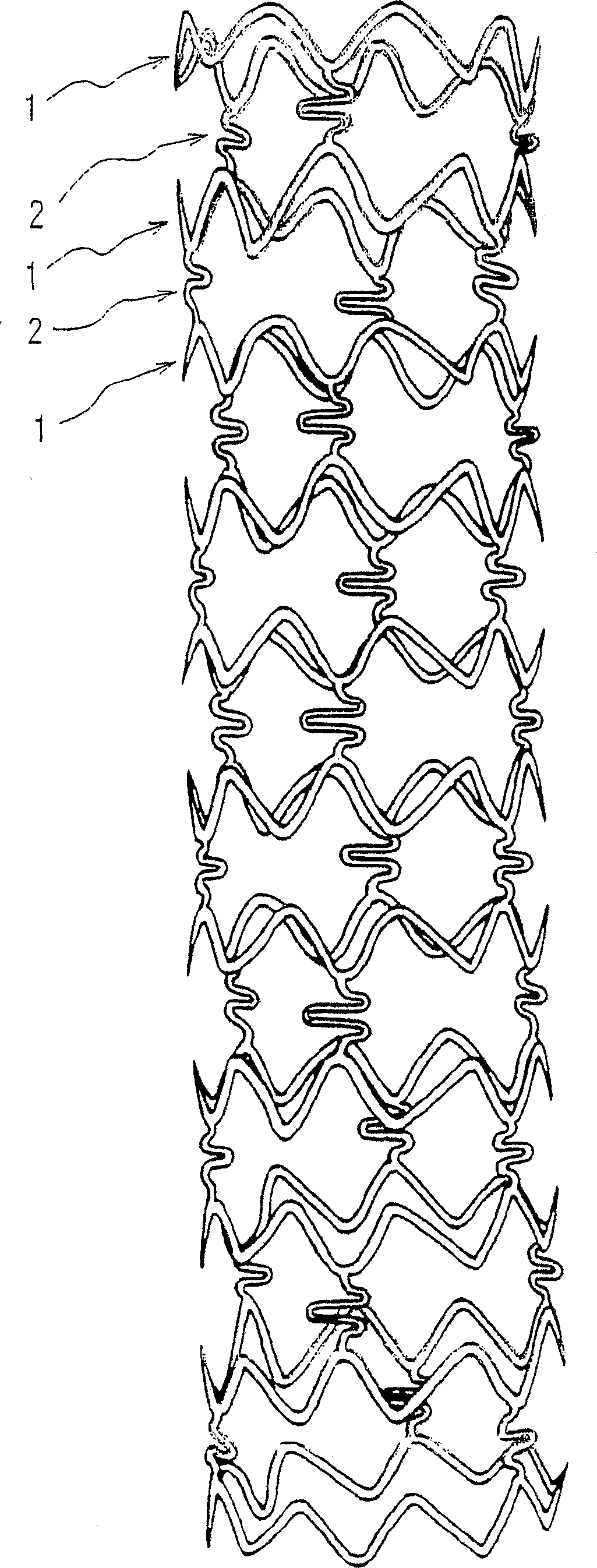
[0044] figure 1 is an enlarged plan view of a stent according to an embodiment of the present invention, figure 2 for figure 1 Deployment of the stent shown, image 3 for showing figure 1 An enlarged plan view of the expanded state of the shown stent, and Figure 4 enlarged for part figure 2 view.
[0045] Such as Figures 1 to 3 As shown, the stent of Example 1 is a tubular member, including eleven ring-shaped members 1 arranged in the longitudinal direction of the stent, used to keep the body cavity open, and three ring-shaped members 1, 1 adjacent in the longitudinal direction. Connecting elements 2 arranged so that they are connected to each other. Each annular member 1 comprises three pieces of first annular member elements 11 and three pieces of second annular member elements 12 which are interconnected alternately in the circumferential direction to define an annular member which is expandable in radial direction.
[0046] Such as figure 2 and 4 As shown, t...
Embodiment 2
[0052] The following will refer to Figure 6 Example 2 of the present invention will be described.
[0053] The stent of Example 2 is a modification of the stent of Example 1, wherein the distance ratio from the radial bisector to the top of the corresponding arched section is set at 7:8, and the arched section 125, 114, 3 and arcuate sections 124, 4, 115 are aligned with each other proximally of the stent at the proximal end of the annular member 5 or distally of the stent at the distal end of the annular member 6, and The connecting element 2 is formed as Figure 5 The shape shown in E. Such as Figure 6 As shown, the stent includes six annular members 1a-1f, which are radially expandable, and two adjacent annular members 1 pass through three such as Figure 5 The corrugated connecting elements 2 shown in E are connected to each other.
[0054] The arcuate segments of the annular member positioned at each end of the stent are aligned along the proximal or distal end of ...
Embodiment 3
[0058] The following will refer to Figure 7 Embodiment 3 of the present invention will be described.
[0059] The stent of Example 3 is a modification of the stent of Example 1, wherein the connection element 2 is formed as Figure 5 The shape shown in D. Such as Figure 7 As shown, the stent includes 10 annular members 1, which are radially expandable and arranged in the direction of the longitudinal axis of the stent, and adjacent annular members 1, 1 pass through three such as Figure 5 The corrugated connecting elements 2 shown in D are connected to each other. The lumen following ability of the above-mentioned scaffold is excellent, because the whole scaffold is flexible enough to respond to bending. Furthermore, it is easy to provide lateral holes for the bracket. In addition, curvature deformation at the top of the arched elements is prevented when the stent is expanded, and the curvature deformation that may occur when the stent is bent is minimized, thereby avoi...
PUM
 Abstract
Description
Claims
Application Information