Oiling nozzle for thrust bearing

Active Publication Date: 2010-08-26
MITSUBISHI HEAVY IND LTD
View PDF9 Cites 22 Cited by
  • Summary
  • Abstract
  • Description
  • Claims
  • Application Information

AI Technical Summary

Benefits of technology

[0013]According to such an oiling nozzle for a thrust bearing, the lubricating oil that has been supplied from the bottom can be efficiently supplied (ejected) toward the adjacent pads, and the like, and the thus supplied lubricating oil can be efficiently supplied to the sliding surfaces of the pads.
[0014]The thrust

Problems solved by technology

This leads to a problem of insufficient follow

Method used


Image

  • Oiling nozzle for thrust bearing
  • Oiling nozzle for thrust bearing
  • Oiling nozzle for thrust bearing

Examples


Example

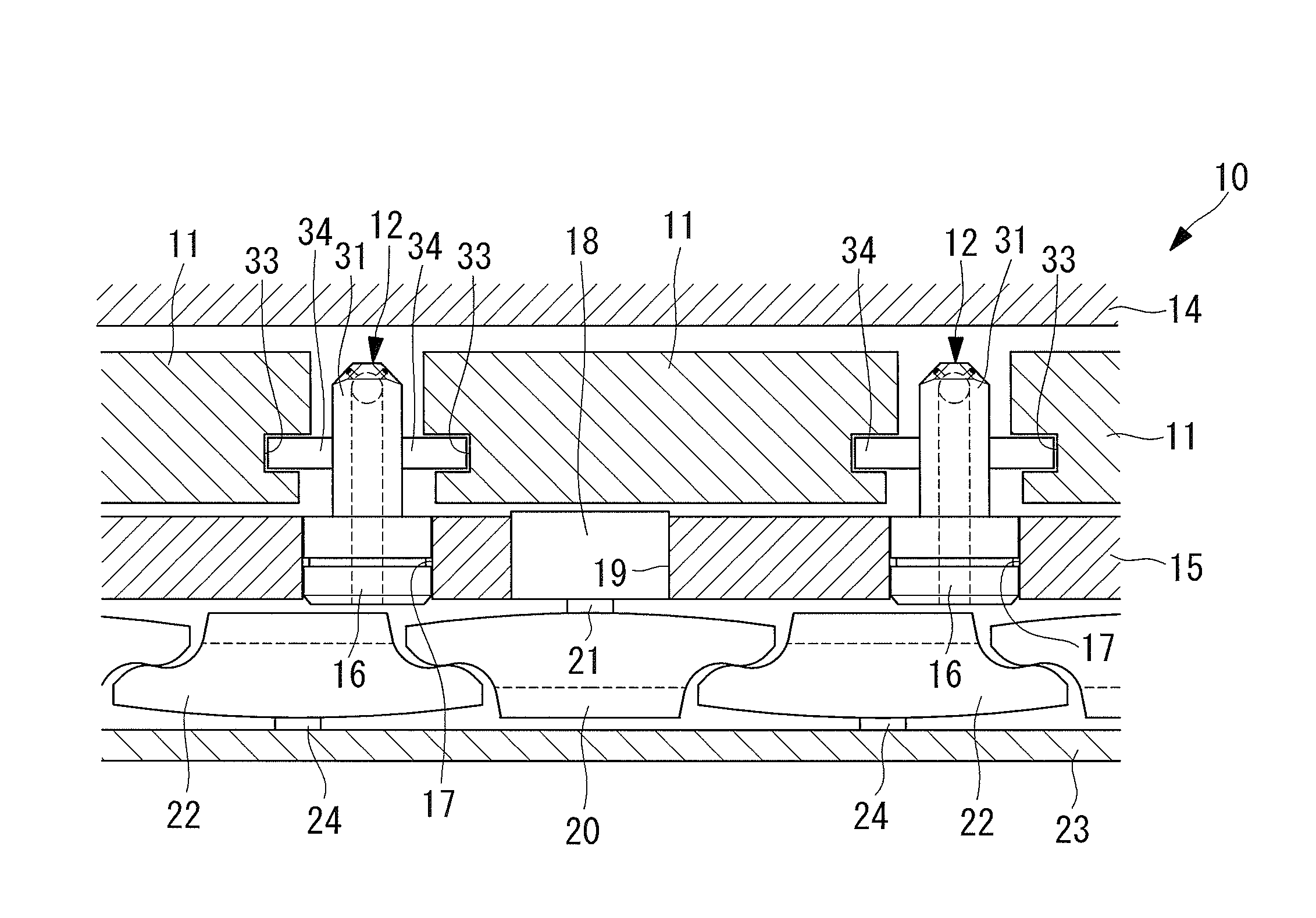
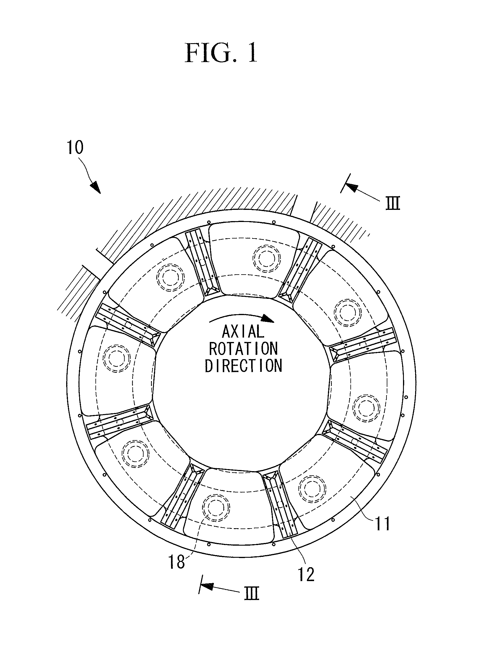
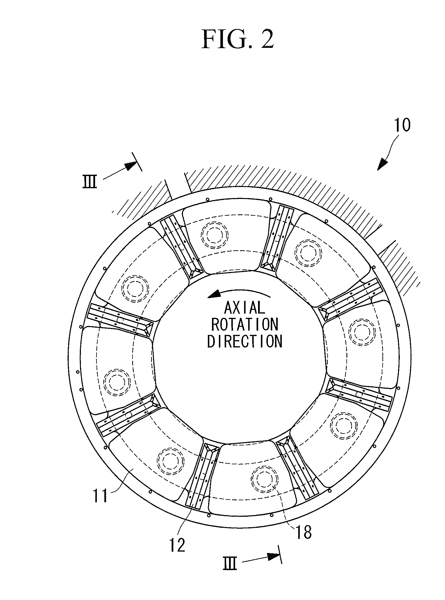
[0028]Hereunder is a description of one embodiment of an oiling nozzle for a thrust bearing according to the present invention (hereinunder, referred to the “oiling nozzle”), with reference to FIG. 1 through FIG. 10.

[0029]FIG. 1 is a front view of a thrust bearing comprising the oiling nozzles according to this embodiment, as well as being a cross sectional view taken along the line I-I of FIG. 3. FIG. 2 is a front view of the thrust bearing comprising the oiling nozzles according to this embodiment, as well as being a cross sectional view taken along the line II-II of FIG. 3. FIG. 3 is a cross sectional view taken along the line III-III of FIG. 1 and FIG. 2. FIG. 4 is a cross sectional view of a part of the thrust bearing comprising the oiling nozzles according to this embodiment, taken along the circumferential direction. FIG. 5 is a side view of the oiling nozzle according to this embodiment. FIG. 6 is a plan view of the oiling nozzle according to this embodiment. FIG. 7 is a bot...


PUM


Abstract

Provided is an oiling nozzle for a thrust bearing, capable of improving the following capability of pads, and achieving a higher bearing pressure of the thrust bearing. An oiling nozzle which is for use in a thrust bearing and is respectively arranged between pads disposed in positions facing the thrust surface of a thrust collar that protrudes radially outward from a rotor shaft, along the circumferential direction, wherein the oiling nozzle comprises: a cylindrical stem; and a rectangular-shaped mainframe whose heightwise middle portions of opposite lateral sides are provided with convex parts each presenting a semicircular disk shape in a plane view, to be fitted into concave parts that are formed in lateral sides of the pads, and whose top portion located on the side opposite to the stem is formed with a plurality of nozzle holes for ejecting lubricating oil that has been supplied from the bottom of the stem toward a space between the thrust collar and the pads.

Description

BACKGROUND OF THE INVENTION[0001]1. Field of the Invention[0002]The present invention relates to an oiling nozzle for a thrust bearing for use in rotating machines such as a steam turbine, a gas turbine, a blower, and a compressor.[0003]This application is based on Japanese Patent Application No. 2009-042656, the content of which is incorporated herein by reference.[0004]2. Description of Related Art[0005]An oiling nozzle for a thrust bearing disclosed in Japanese Unexamined Utility Model Application, Publication No. Sho 63-178622 is known as an example of an oiling nozzle for a thrust bearing for use in a steam turbine.BRIEF SUMMARY OF THE INVENTION[0006]However, regarding such a conventional oiling nozzle for a thrust bearing, a lateral side of the oiling nozzle and a lateral side of a pad are contacted by surfaces (surface-to-surface contact). For this reason, the pad can not be rotated about an axis parallel to the rotation axis of the rotor shaft (rotation shaft). This leads to...

Claims


Application Information

Patent Timeline
IPC IPC(8): F16C17/24
CPCF01D25/18F16C17/06F16C33/1045F16C33/1085F16C2360/23F05D2240/52F05D2250/12F05D2250/231F05D2250/712F16C41/02F16C2360/00F01D25/16F16C33/10
Inventor WAKI, YUICHIRONAKANO, TAKASHIKAIKOGI, TAKAAKI
Owner MITSUBISHI HEAVY IND LTD
Why Eureka
Try Eureka