Power for thermal spraying, thermal spraying method, and thermally sprayed coating
Active Publication Date: 2018-05-03
OERLIKON METCO JAPAN LTD
View PDF5 Cites 0 Cited by
Summary
Abstract
Description
Claims
Application Information
AI Technical Summary
This helps you quickly interpret patents by identifying the three key elements:
Problems solved by technology
Method used
Benefits of technology
Benefits of technology
The present invention provides a powder for thermal spraying that can be efficiently supplied through a powder supplier of a thermal spraying apparatus, prevent variation and pulsation, and achieve a required film forming rate, to form a denser coating onto the surface of the substrate to be thermally sprayed. The invention also allows for the creation of thermal spray coatings with various properties such as durability, corrosion resistance, abrasion resistance, erosion resistance, thermal resistance, and thermal shock resistance. Additionally, the invention provides a method for thermal spraying with this powder to achieve the desired properties in the resulting coating.
Problems solved by technology
However, it is known that the above conventional powder supplying apparatus has a drawback that when the particle diameter of the powder for thermal spraying is 10 μm or smaller, the flowability of the powder is lowered, which causes pulsation and obstruction in supply tube of the powder supplying apparatus.
Thus, in view of minimization of time and cost consumption increasing the powder supplying amount is theoretically disadvantageous when compared to the case where dried powder alone is supplied.
Method used
Image
Click on the blue label to locate the original text in one second.
Reading with bidirectional positioning of images and text.
Examples
example 1
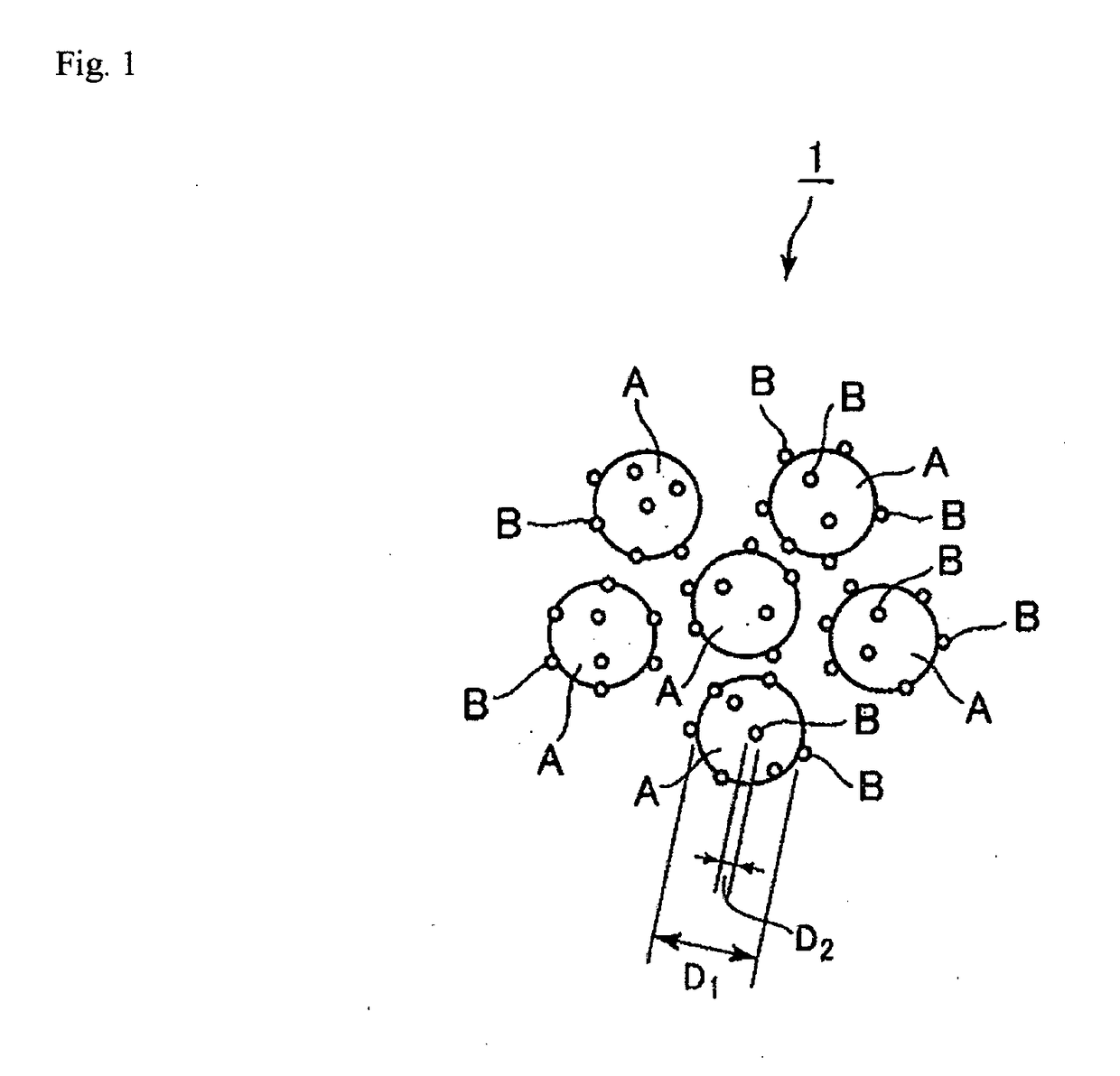
[0031]As shown in FIG. 1, the powder for thermal spraying 1 of the present invention is a powder mixture obtained by mixing ceramic powder A having a large particle diameter D1 and ceramic powder B having a small particle diameter D2, in which the ceramic powder B adheres to the surface of the ceramic powder A.
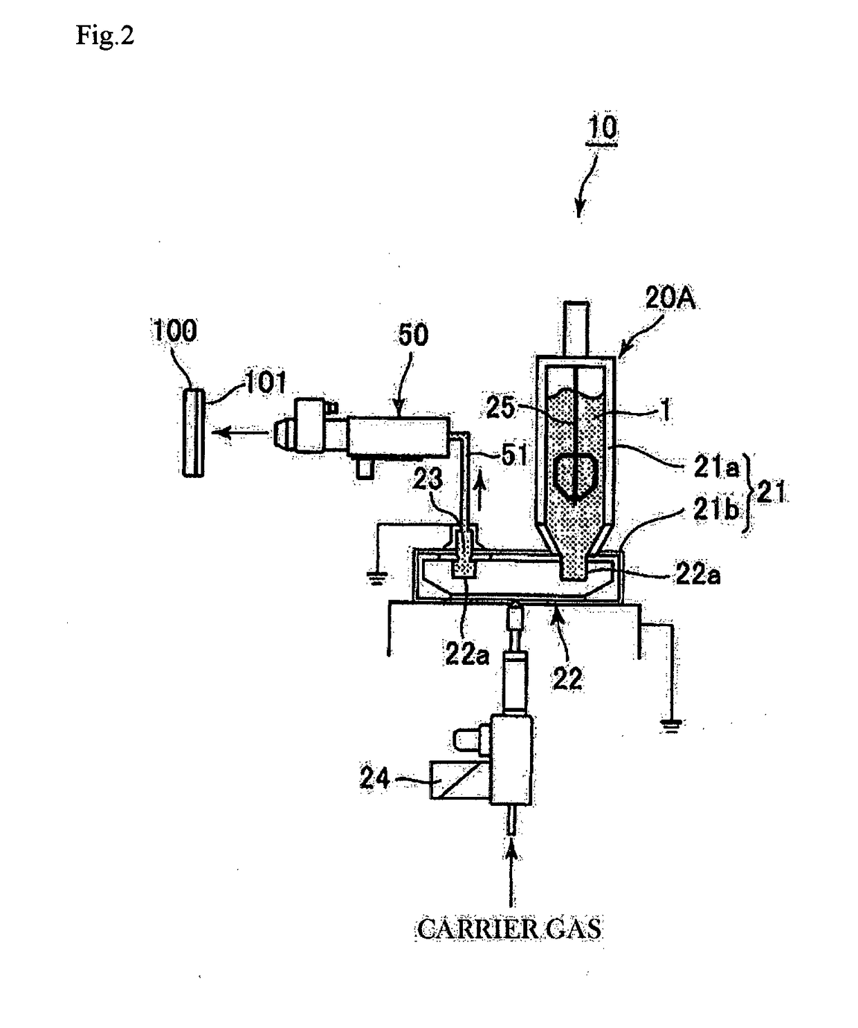
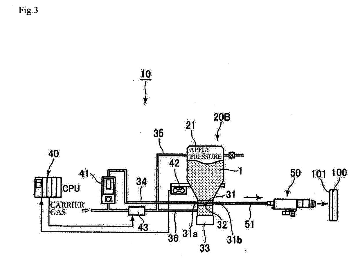
[0032]The powder for thermal spraying 1 of the present invention is preferably used for a thermal spraying apparatus 10 using a powder supplying apparatus 20 (20A, 20B) which is well-known to those skilled in the art, including a disk-type powder supplier 20A as shown in FIG. 2 (e.g., “Metco Single / Twin-120 (tradename), product of Oerlikon Metco Ltd.) or a fluidized-bed type powder supplier 20B as shown in FIG. 3 (e.g., “Metco 9MP” (tradename), product of Oerlikon Metco Ltd.).
[0033]As for the thermal spraying apparatus 10, this spraying apparatus 10 uses a disk-type powder supplier 20A as a powder supplying apparatus 20. The disk-type powder supplier 20A is equipped with a con...
(A) First experiments (Experimental Examples 1 to 12 and Comparative Examples 1 to 8)
[0073]In Experimental Examples 1 to 12 and Comparative Examples 1 to 8, as shown in Tables 1 and 2, alumina A, B, C, and D were used as the ceramic powder A and a fumed alumina was used as the ceramic powder B.
[0074]Also, in Experimental Examples 1 to 12 and Comparative Examples 1 to 8, the particle diameters (D1, D2) and weights (W1, W2) of the ceramic powder A and the ceramic powder B, and an addition ratio (Y) (represented by % by weight) of the ceramic powder B are as shown in Tables 1 and 2.
[0075]A powder mixture was obtained by adding a prescribed amount of the ceramic powder B to a prescribed amount of the ceramic powder A as shown in Tables 1 and 2, and stirring the admixture for 5 minutes with V-type mixer (tradename: “VM-2L type,” product of Tsutsui Scientific Instruments, Co., Ltd.). After stirring, the powder mixture was subjected to a flowability test...
example 2
[0093]Thermal spraying was conducted onto the substrate to be thermally sprayed 100 by using the powder for thermal spraying 1 of the present invention which was described in Example 1. In the present Example, plasma spraying, which is a method of thermally spraying utilizing high temperature and high pressure plasma generated by discharging while causing an inert gas to flow between electrodes, was adopted. The powder supplying apparatus 20 used was “Metco Twin-120-A” (tradename), product of Oerlikon Metco Ltd., which is a disk-type powder supplier 20A by which the flowing tests were made, and “TriplexPro-210” (tradename), product of Oerlikon Metco Ltd., equipped with a nozzle of 6.5 mm, 9 mm was used as the thermal sprayer (plasma spray gun) 50.
[0094]As the substrate to be thermally sprayed 100, stainless steel (SUS304) was used, and this was subjected to pretreatment for roughening the substrate surface by grid blast. By the pretreatment, the surface roughness Rz of the substrate...
PUM
Property
Measurement
Unit
Fraction
aaaaa
aaaaa
Fraction
aaaaa
aaaaa
Fraction
aaaaa
aaaaa
Abstract
To provide powder for thermal spraying, a method of thermal spraying, and a thermally sprayed coating, which can efficiently work supplying of a dry state powder by using a powder supplying apparatus with a thermal spraying apparatus, and which prevent variation and pulsation or lowering of supplied amount of powder and achieve a required film forming rate, and can obtain a denser coating on the surface of the substrate to be thermally sprayed. [Solution] Powder for thermal spraying 1 is a powder mixture obtained by mixing ceramic powder A whose particle diameter is D1 and ceramic powder B whose particle diameter is D2, wherein D1 is 0.5 to 12 μm as a median diameter, D2 is 0.003 to 0.100 μm as an average particle diameter converted from the BET specific surface area, and when, in the powder mixture, the total weight of the ceramic powder A to be used whose prescribed particle diameter D1 is W1, and the total weight of the ceramic powder B to be added to the ceramic powder A is W2, an addition ratio Y of the ceramic powder B defined by Y=W2 / (W1+W2) satisfies: Y≥0.2066×D1−0.751 and Y≤0.505×D1−0.163.
Description
TECHNICAL FIELD[0001]The present invention relates to powders for thermal spraying used as a raw material for thermal spraying material such as plasma spraying and high velocityflame spraying, a method of thermal spraying using the powder for thermal spraying, and thermally sprayed coating.BACKGROUND ART[0002]Conventionally, it has been carried out to form a film by applying thermal spraying with plasma spraying or high velocityflame spraying onto the surface of a substrate by using, for example, ceramic powder as a raw material for a thermal spraying material, to improve abrasion resistance, thermal resistance, etc. of the surface of a substrate to be thermally sprayed, such as metal as an object of spraying.[0003]Currently, as ceramic powder, powder for thermal spraying whose average particle diameter is about 20 to 60 μm is normally used, but in the case where a denser coating is required on the surface of the substrate to be thermally sprayed, a powder whose average particle d...
Claims
Application Information
Patent Timeline
Application Date:The date an application was filed.
Publication Date:The date a patent or application was officially published.
First Publication Date:The earliest publication date of a patent with the same application number.
Issue Date:Publication date of the patent grant document.
PCT Entry Date:The Entry date of PCT National Phase.
Estimated Expiry Date:The statutory expiry date of a patent right according to the Patent Law, and it is the longest term of protection that the patent right can achieve without the termination of the patent right due to other reasons(Term extension factor has been taken into account ).
Invalid Date:Actual expiry date is based on effective date or publication date of legal transaction data of invalid patent.

