Railcar including car-body tilting system and train set

Active Publication Date: 2018-10-18
KAWASAKI RAILCAR MFG CO LTD
View PDF0 Cites 3 Cited by
  • Summary
  • Abstract
  • Description
  • Claims
  • Application Information

AI Technical Summary

Benefits of technology

The present invention allows for efficient supply of pressurized air even when the main tank pressure lowers. This is useful for railcars or train sets.

Problems solved by technology

As a result, the pressure of the pressurized air in the main tank lowers, and this deteriorates operation responsiveness of the car-body tilting system.

Method used


Image

  • Railcar including car-body tilting system and train set
  • Railcar including car-body tilting system and train set
  • Railcar including car-body tilting system and train set

Examples


embodiment 1

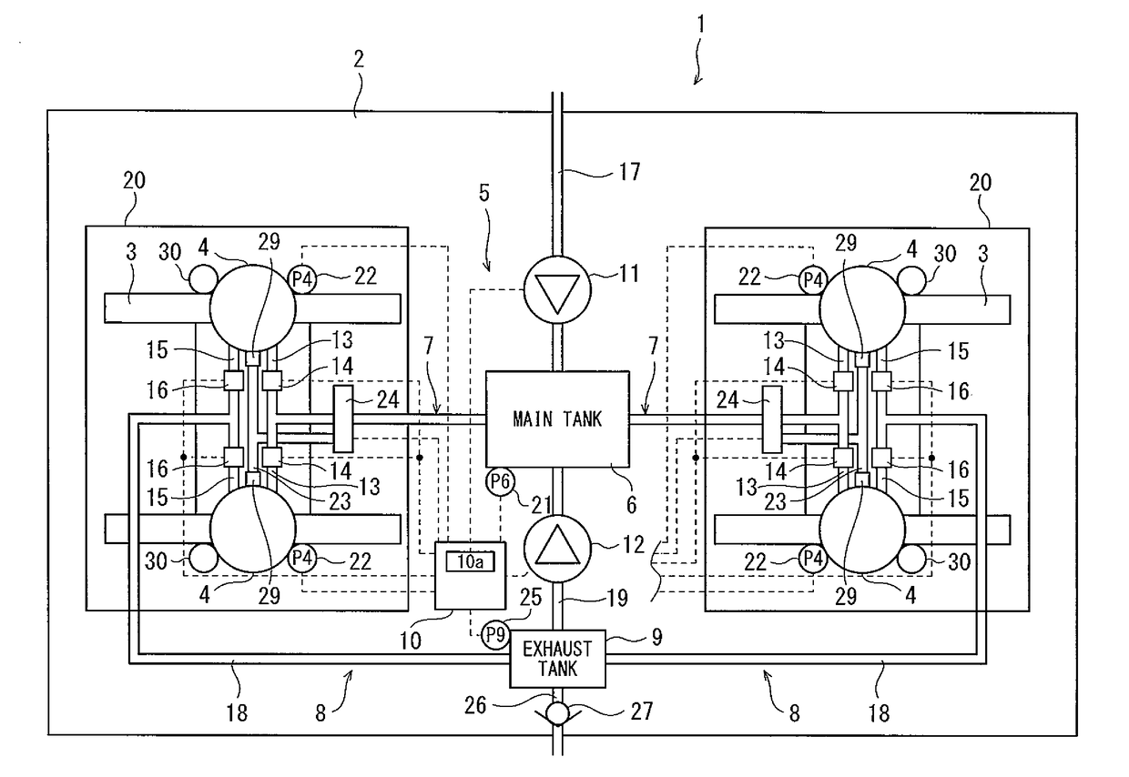
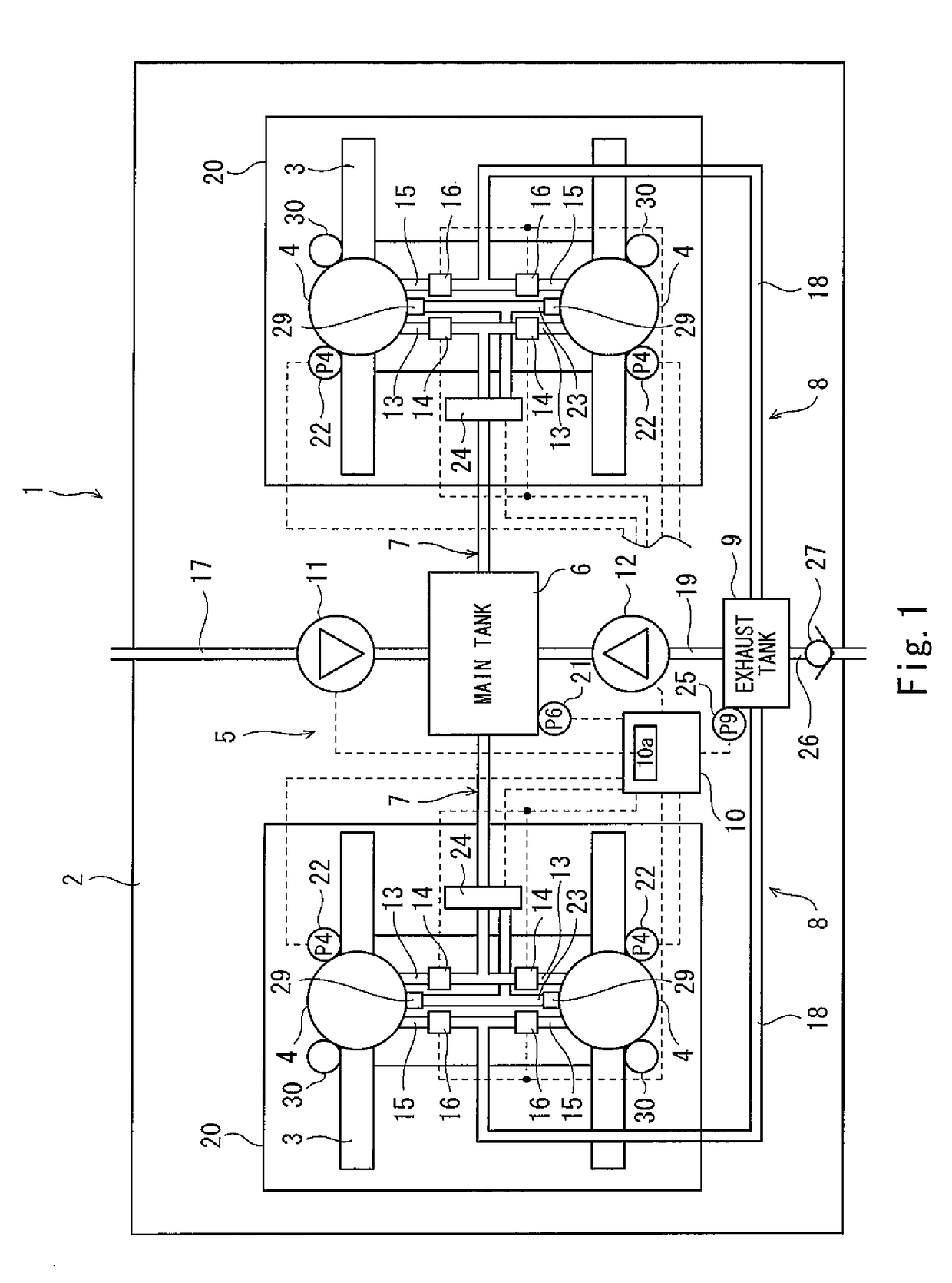
[0019]FIG. 1 is a plan view showing a schematic structure of a railcar in Embodiment 1. As shown in FIG. 1, a railcar 1 in the present embodiment includes: a carbody 2 on which passengers get; and a bogie frame 3 supporting wheels (not shown). A pair of air springs 4 are provided between the carbody 2 and the bogie frame 3 so as to be located at both respective car width direction sides. In the railcar 1, two bogie frames 3 are provided for one carbody 2 so as to be lined up in the car longitudinal direction, and a pair of air springs 4 are provided for one bogie frame 3. As each of the air springs 4, a known component such as a diaphragm type air spring is adopted.

[0020]The railcar 1 includes a car-body tilting system capable of tilting the posture of the carbody 2 with respect to the bogie frames 3 when the railcar 1 travels through a curved line. A car-body tilting system 5 includes: a main tank 6 storing air (pressurized air) supplied to two pairs of air springs 4; air supply pa...

embodiment 2

[0050]FIG. 3 is a plan view showing a schematic structure of the railcar in Embodiment 2. In the present embodiment, the same reference signs are used for the same components as in Embodiment 1, and explanations of such components are omitted. As shown in FIG. 3, a car-body tilting system 5B of a railcar 1B in the present embodiment is different from Embodiment 1 in that an air release exhaust valve 27B configured to release the discharged pressurized air from the exhaust tank 9 to the atmosphere is constituted by a solenoid valve capable of changing relief pressure.

[0051]The control portion 10 serves as an exhaust valve the control portion 10b configured to perform the operation control of the air release exhaust valve 27B. When the internal pressure P9 of the exhaust tank 9 is higher than a fifth threshold Pth5 (Pth5>Pth3), the control portion 10 performs a control operation of opening the air release exhaust valve 27B to open the exhaust tank 9 to an outside. When the internal pr...

embodiment 3

[0067]FIG. 4 is a plan view showing a schematic structure of the train set in Embodiment 3. In the present embodiment, the same reference signs are used for the same components as in Embodiment 1, and explanations of such components are omitted.

[0068]Each of Embodiments 1 and 2 explains a case where one railcar 1 includes the first compressor 11 and the second compressor 12. However, when applying Embodiment 1 or 2 to an existing railcar, i.e., to the configuration of PTL 1 or to a railcar including only a normal atmosphere introducing compressor (first compressor 11), it is difficult in some cases to add the second compressor 12 to the layout of the existing railcar in terms of space.

[0069]Therefore, the present embodiment will explain an example for providing a train set configured such that the car-body tilting system of the railcar which system is capable of efficiently supplying the discharged pressurized air even when the internal pressure of the main tank lowers can be relati...


PUM


Abstract

A main tank storing pressurized air supplied to a pair of air springs; an air supply passage through which the pressurized air flows between the main tank and each of the pair of air springs; a plurality of compressors configured to supply the pressurized air to the main tank; an air discharge passage which is connected to the pair of air springs and through which discharged pressurized air discharged from the air springs flows; and an exhaust tank connected to the air discharge passage and storing the discharged pressurized air discharged from the air springs, the plurality of compressors including at least one first compressor configured to pressurize air introduced from an atmosphere and at least one second compressor configured to operate auxiliarily for an operation of the first compressor and pressurize the discharged pressurized air introduced from the exhaust tank.

Description

TECHNICAL FIELD[0001]The present invention relates to a railcar including a car-body tilting system and a train set.BACKGROUND ART[0002]Proposed is a car-body tilting system capable of tilting the posture of a carbody with respect to a bogie when a railcar travels through a curved line. As such car-body tilting mechanism of the railcar, there is an air spring type car-body tilting mechanism configured such that air springs are provided between the bogie and the carbody.[0003]Generally, the air springs of the car-body tilting system are connected to a main tank (main reservoir) capable of storing compressed air (hereinafter referred to as “pressurized air”) supplied from a compressor mounted on the railcar, the compressor being provided as a drive power source for a brake of a car, a car door, and the like. When the railcar travels through a curved section, the air spring at an outer rail side and the main tank communicate with each other, and the pressurized air is introduced to the...

Claims


Application Information

Patent Timeline
IPC IPC(8): B61F5/24B61F5/10
CPCB61F5/24B61F5/10B61F5/22B60G2300/10B60G2500/205
Inventor YAMADA, TADASHIYOSHIMATSU, YUTA
Owner KAWASAKI RAILCAR MFG CO LTD
Why Eureka
Try Eureka