Working machine

A technology for working machines and working machines, which is applied to mechanically driven excavators/dredgers, earthmoving machines/shovels, lifting devices, etc., and can solve problems such as inability to maintain angular characteristics, deviations, and angle deviations of attachments

Inactive Publication Date: 2006-08-30
KOMATSU LTD
View PDF3 Cites 8 Cited by
  • Summary
  • Abstract
  • Description
  • Claims
  • Application Information

AI Technical Summary

Problems solved by technology

[0019] However, in the wheel loader disclosed in Patent Document 1, the angle characteristics of the bucket are improved by specifying the pivot positions of the vehicle body and the hydraulic cylinder for dumping. In this case, after turning the boom to raise the bucket, the angle of the attachment at the highest position deviates greatly on the positive side (the side opposite to the dumping side), resulting in a problem that the angle characteristic cannot be maintained
[0020] Such problems even in Figure 35 Among the conventional wheel loaders shown, such as Figure 36 The same would result as shown, and, in Figure 37 In the wheel loader shown in Patent Document 2, such as Figure 38 as shown also produces
In particular, in the wheel loader of Patent Document 2, ( Figure 37 , 38 ), unlike other wheel loaders, the hydraulic cylinder for dumping (refer to the dot-dash line) is pivotally supported by the boom 10, and since the positional relationship between the hydraulic cylinder for dumping and the boom 10 is completely different even when the boom 10 is rotated, Therefore, regardless of whether the bucket 20 is tilted on the ground or not, as the bucket 20 rises, the angle of its attachments also deviates greatly on the positive side as it is, and the soil, etc. handled by the bucket 20 increases with the orientation. position, while overflowing to the body side

Method used


Image

  • Working machine
  • Working machine
  • Working machine

Examples


no. 1 approach

[0150] Next, a first embodiment of the present invention will be described with reference to the drawings.

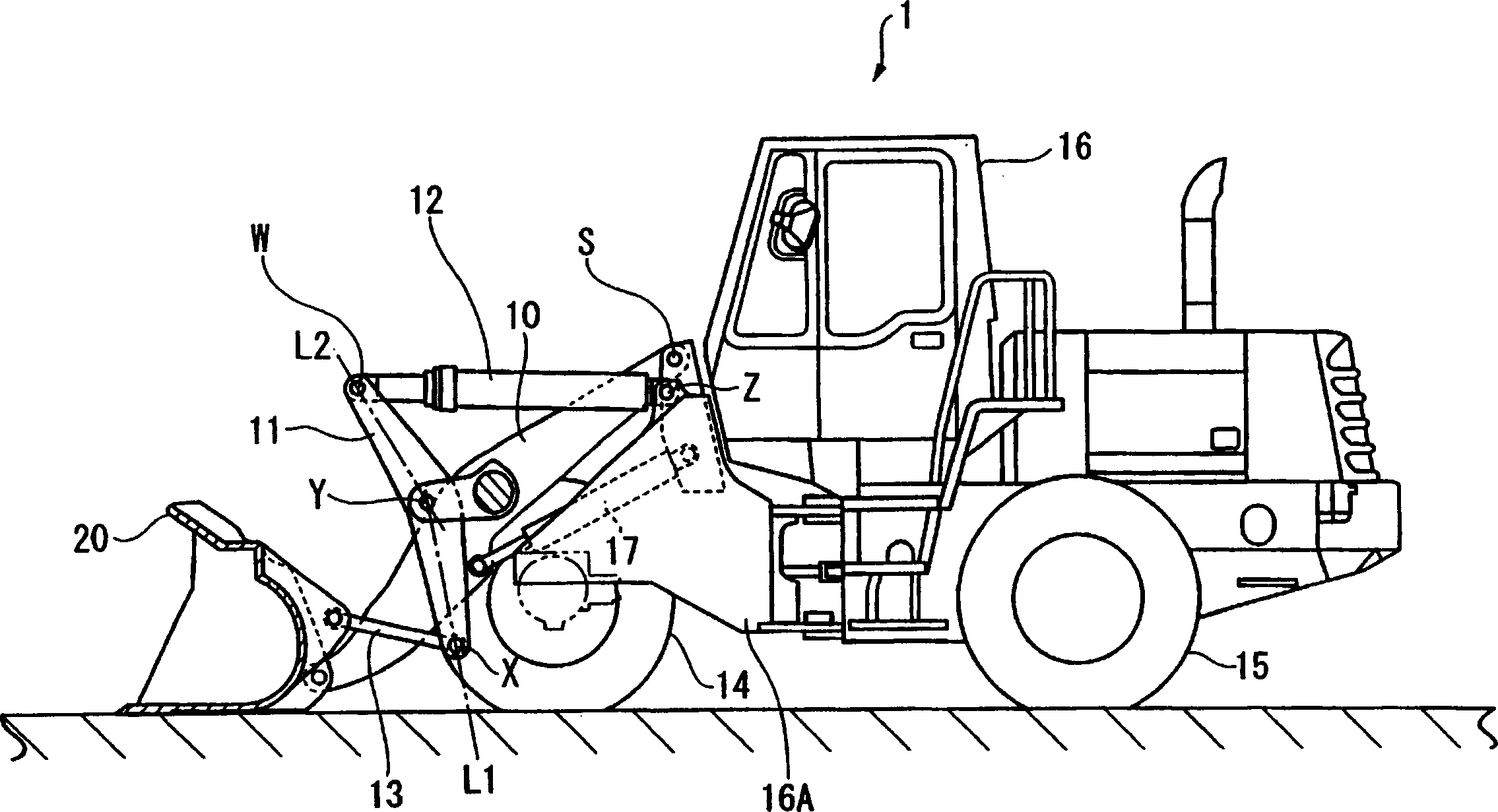
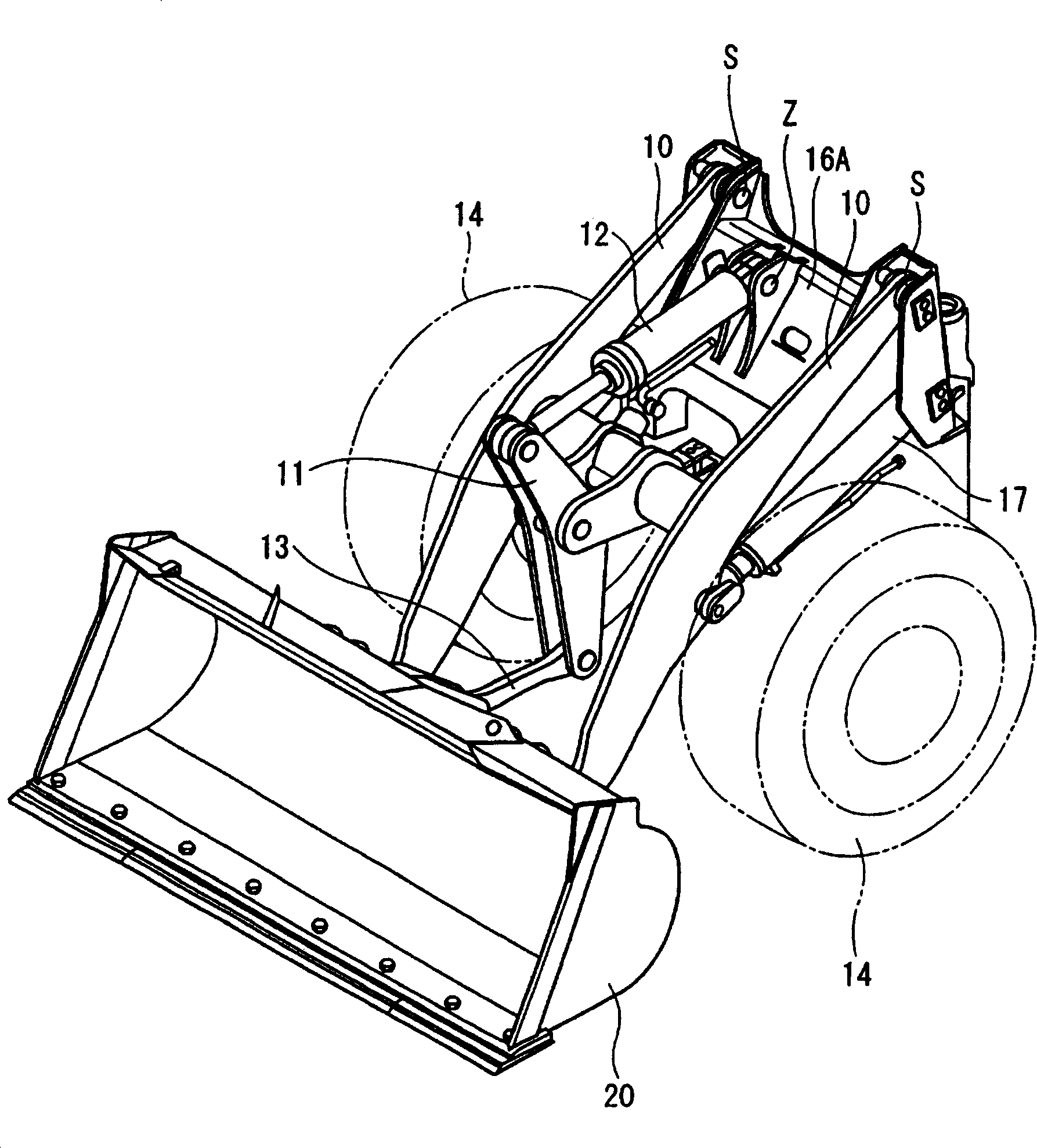
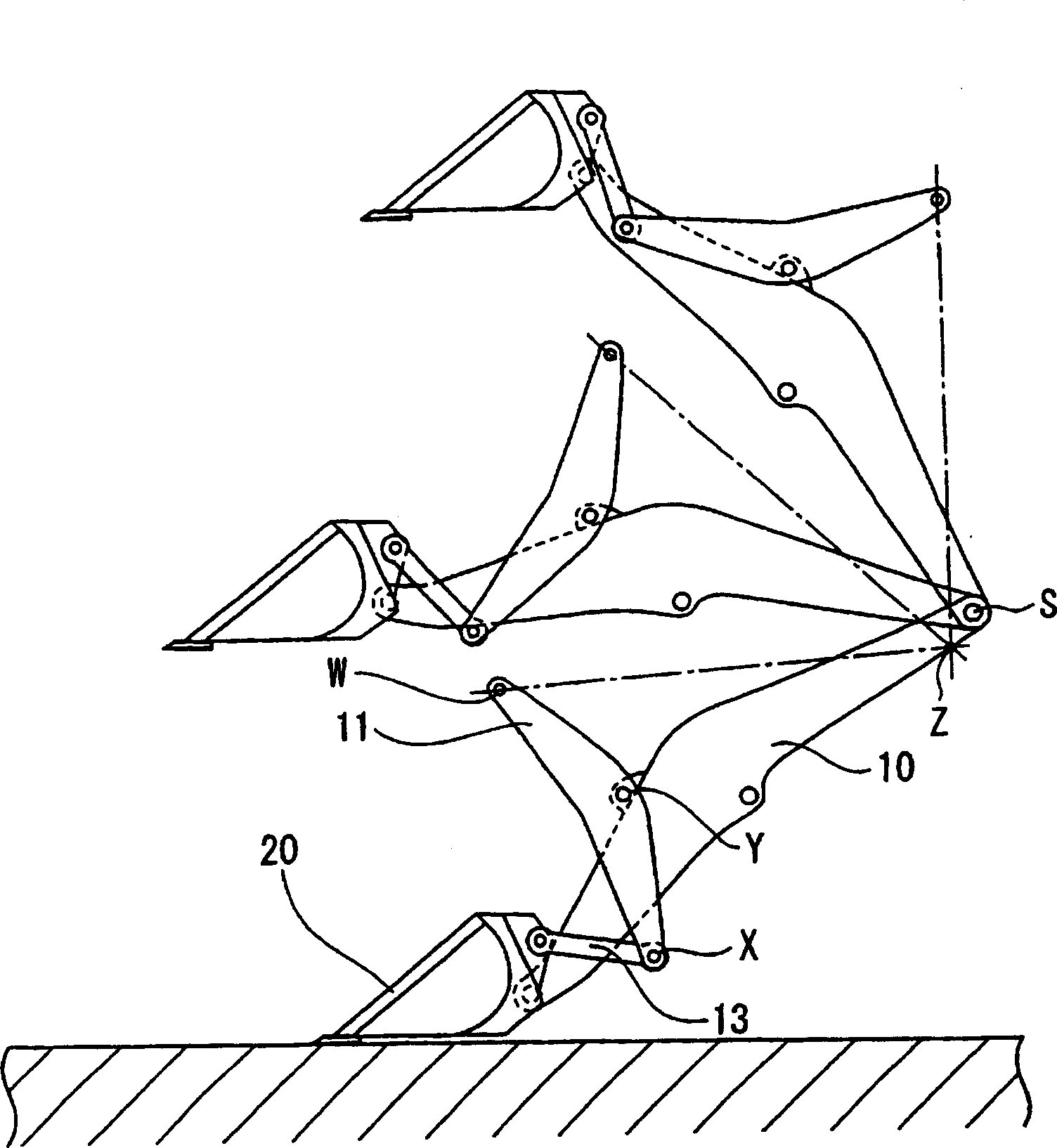
[0151] figure 1 It is a side view showing the whole of the wheel loader (working machine) 1 according to this embodiment, figure 2 is an external perspective view showing the working machine portion of the wheel loader 1, image 3 , 4It is a figure which shows the movement of the main part of a wheel loader. In addition, in each figure, the same code|symbol is attached|subjected to the component already demonstrated in background art.

[0152] The wheel loader 1 has a self-propelled vehicle body 16 on front and rear tires 14, 15, and is equipped with a structure 16A of a working machine including a bucket 20 supported in front of the vehicle body 16 (left side in the drawing), and a bucket 20. 20 driving boom 10 and a Z rod-shaped connecting rod type connection mechanism.

[0153] The base end of the boom 10 is pivotally supported by a structure 16A, driven by a ...

no. 2 approach

[0181] exist Figure 10 2 shows a second embodiment of the present invention, that is, a wheel loader 2 in which forks (forks) 30 are mounted instead of the bucket 20 of the first embodiment. The other structures are substantially the same as those of the first embodiment.

[0182] In such a wheel loader 2, the fork 30 is mounted at substantially the same position as that of the bucket 20 in the first embodiment, so the attachment angle of the fork 30 mounted horizontally on the ground is the same as that of the first embodiment. The bucket 20 according to one embodiment also maintains good angular characteristics without deviation up to the highest position.

[0183] Furthermore, according to the wheel loader 2, the line segment L2 is inclined toward the fork 30 side with respect to the line segment L1 of the rocker 11, so that the inclination force at the highest position becomes smaller than that of the wheel loader disclosed in Patent Document 3. Large, tilting force cha...

no. 3 approach

[0192] exist Figure 13 In , the wheel loader 3 according to the third embodiment of the present invention is shown. exist Figure 14 In , the figure showing the use of the bucket (attachment) 20 among the two types of attachments prepared in advance is shown in Figure 15 In , a figure using a fork (attachment) 30 is shown. Any one of these buckets 20 and forks 30 may be attached for a dedicated work, or may be selectively used depending on the work.

[0193] In addition, in this embodiment, if Figure 14 , 15 , 16, the pivot position Q of the bucket 20 and the connecting link 13 and the pivot position Q of the fork 30 and the connecting link 13 are set to be different from the pivot position P of the bucket 10. position. The pivot position Q of the fork 30 is set to be slightly offset to a position where the dumping hydraulic cylinder 12 moves in and out compared to the case of the bucket 20 . As a result, the tilting force when the fork 30 is used is further increase...


PUM


Abstract

In a wheel loader 3, an angle formed by a first line segment L1 connecting a pivot position Y on a boom 10 of a bell crank 11 and a pivot position X on a connecting link 13 and a second line segment L2 connecting the pivot position Y on the boom 10 of the bell crank 11 and a pivot position W on a tilt cylinder 12 is set in a range from 0 degree to 180 degrees on the attachment 20, 30 side, the attachment can be selected from a plurality of types such as a bucket 20 and a fork 30 for use, and each of the attachment 20, 30 that is different from each other has a different pivot position on the connecting link 13 relative to the pivot position on the boom 10 as a reference point.

Description

technical field [0001] The invention relates to a work machine. Background technique [0002] Conventionally, it is known to use a wheel loader as a working machine. In the wheel loader, attachments such as buckets are set on the front end of the boom, which is pivotally supported on the vehicle body and set in such a way that the boom cylinder can move up and down, the bucket passes through The so-called Z bar linkage is driven. [0003] Such as Figure 35 As shown, the Z bar-shaped link is composed of a rocker 11 pivotally supported in the approximate center of the boom 10 in a rotatable manner, and a hydraulic cylinder ( Refer to the dashed line), and the connecting link 13 connecting the other end side of the rocker 11 and the back of the bucket 20 . [0004] In addition, in Figure 35 In , the illustration of the boom cylinder and the hydraulic cylinder for dumping is omitted in order to avoid the complexity of the drawing. In addition, in the drawing, the pivot pos...

Claims


Application Information

Patent Timeline
Patent Type & Authority Applications(China)
IPC IPC(8): E02F3/34B66F9/24B66F9/065E02F3/43
CPCB66F9/065E02F3/433E02F3/3411E02F3/432
Inventor 小山内仁野濑松男
Owner KOMATSU LTD
Why Eureka
Try Eureka