Working machine
A technology for operating machinery and operating machines, applied to mechanically driven excavators/dredgers, earth movers/shovels, lifting devices, etc., can solve problems such as inability to maintain angle characteristics, deviation, overflow, etc.
- Summary
- Abstract
- Description
- Claims
- Application Information
AI Technical Summary
Problems solved by technology
Method used
Image
Examples
no. 1 approach
[0166] Next, a first embodiment of the present invention will be described with reference to the drawings.
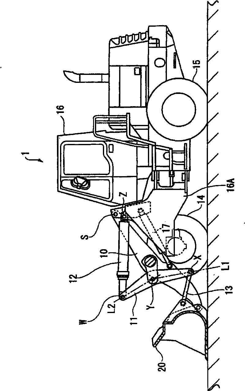
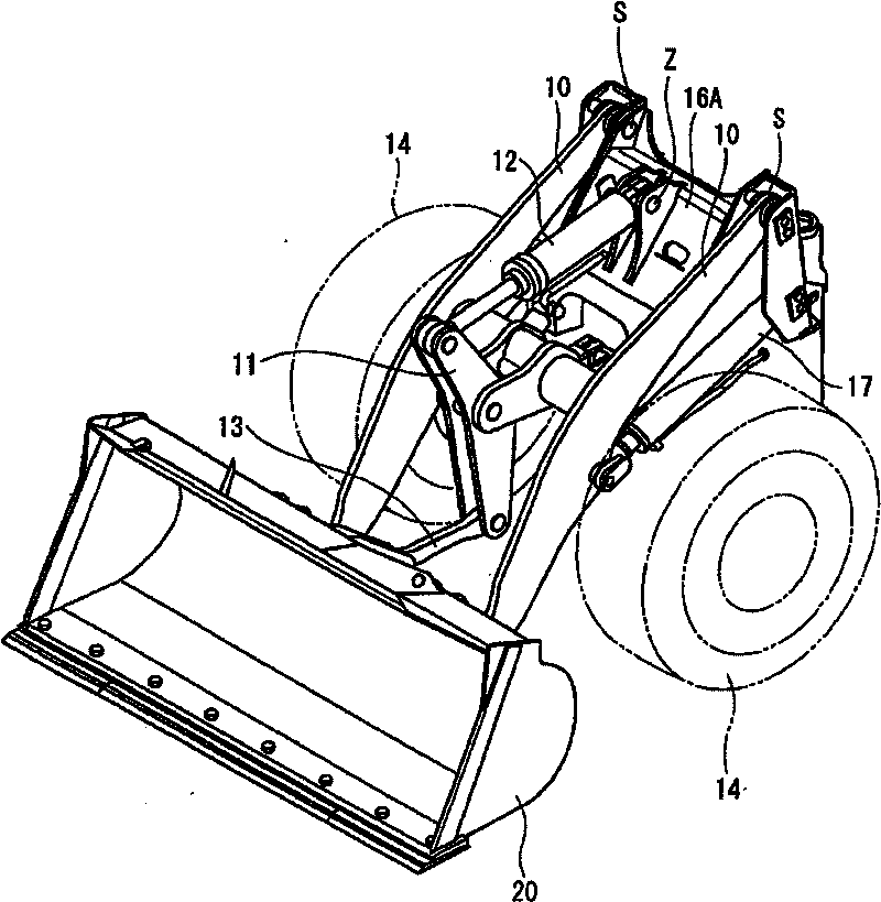
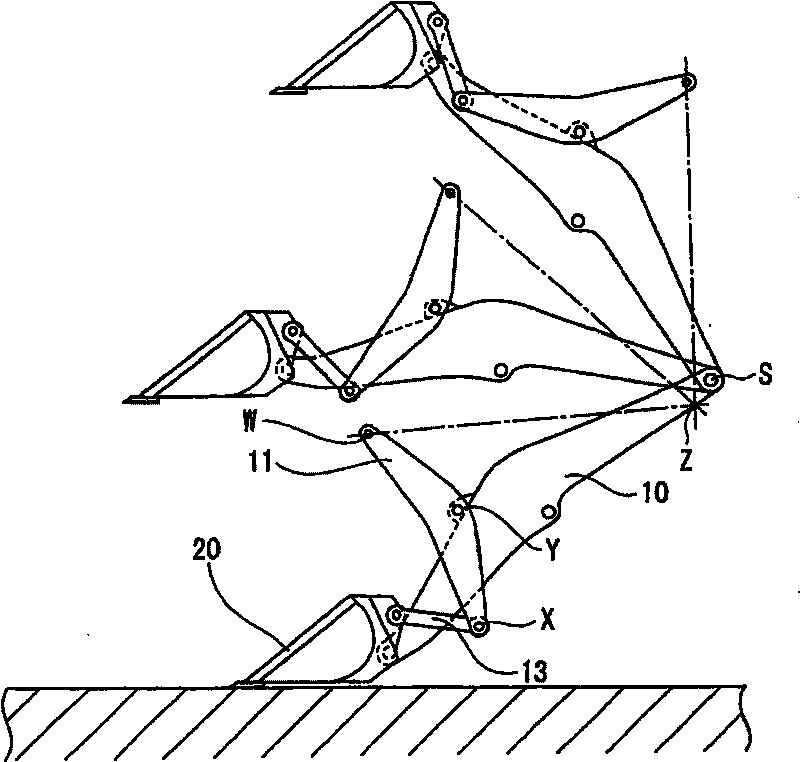
[0167] figure 1 It is a side view showing the whole of the wheel loader (working machine) 1 according to this embodiment, figure 2 is an external perspective view showing the working machine portion of the wheel loader 1, image 3 , 4 It is a figure which shows the movement of the main part of a wheel loader. In addition, in each figure, the same code|symbol is attached|subjected to the component already demonstrated in background art.
[0168] The wheel loader 1 has a self-propelled vehicle body 16 on front and rear tires 14, 15, and is equipped with a structure 16A of a working machine including a bucket 20 supported in front of the vehicle body 16 (left side in the drawing), and a bucket 20. 20 driving boom 10 and a Z rod-shaped connecting rod type connection mechanism.
[0169] The base end of the boom 10 is pivotally supported by a structure 16A, driven by a...
no. 2 approach
[0197] exist Figure 10 2 shows a second embodiment of the present invention, that is, a wheel loader 2 in which forks (forks) 30 are mounted instead of the bucket 20 of the first embodiment. The other structures are substantially the same as those of the first embodiment.
[0198] In such a wheel loader 2, the fork 30 is mounted at substantially the same position as that of the bucket 20 in the first embodiment, so the attachment angle of the fork 30 mounted horizontally on the ground is the same as that of the first embodiment. The bucket 20 according to one embodiment also maintains good angular characteristics without deviation up to the highest position.
[0199] Furthermore, according to the wheel loader 2, the line segment L2 is inclined toward the fork 30 side with respect to the line segment L1 of the rocker 11, so that the inclination force at the highest position becomes smaller than that of the wheel loader disclosed in Patent Document 3. Large, tilting force cha...
no. 3 approach
[0208] exist Figure 13 In , the wheel loader 3 according to the third embodiment of the present invention is shown. exist Figure 14 In , the figure showing the use of the bucket (attachment) 20 among the two types of attachments prepared in advance is shown in Figure 15 In , a figure using a fork (attachment) 30 is shown. Any one of these buckets 20 and forks 30 may be attached for a dedicated work, or may be selectively used depending on the work.
[0209] In addition, in this embodiment, if Figure 14 , 15 , 16, the pivot position Q of the bucket 20 and the connecting link 13 and the pivot position Q of the fork 30 and the connecting link 13 are set to be different from the pivot position P of the bucket 10. position. The pivot position Q of the fork 30 is set to be slightly offset to a position where the dumping hydraulic cylinder 12 moves in and out compared to the case of the bucket 20 . As a result, the tilting force when the fork 30 is used is further increase...
PUM
 Abstract
Description
Claims
Application Information
 - R&D
- Intellectual Property
- Life Sciences
- Materials
- Tech Scout
- Unparalleled Data Quality
- Higher Quality Content
- 60% Fewer Hallucinations
Browse by: Latest US Patents, China's latest patents, Technical Efficacy Thesaurus, Application Domain, Technology Topic, Popular Technical Reports.
© 2025 PatSnap. All rights reserved.Legal|Privacy policy|Modern Slavery Act Transparency Statement|Sitemap|About US| Contact US: help@patsnap.com


