
Attenuation sampling device used for large-angle high-energy laser incidence

A high-energy laser and sampling device technology, applied in measuring devices, photometry, optical radiation measurement, etc., can solve difficult problems such as laser light intensity attenuation and parameter measurement, increasing the distance of detector arrays, and reducing the ability to absorb heat. , to improve the ability to resist laser radiation, improve the incidence angle characteristics, and improve the effect of surface reflectivity

Active Publication Date: 2014-09-03
NORTHWEST INST OF NUCLEAR TECH
View PDF5 Cites 9 Cited by
  • Summary
  • Abstract
  • Description
  • Claims
  • Application Information

AI Technical Summary

Problems solved by technology

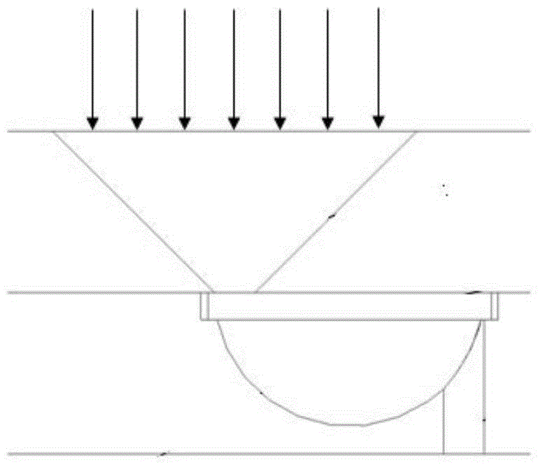
The problem with this processing method is that a large-angle conical hole is hollowed out on the front panel that needs to withstand strong laser irradiation, especially for area array structure detection, which means that the mass of the front panel is reduced and the ability to absorb heat Therefore, the anti-laser damage ability of the front panel is weakened, so that the detector array is easily damaged when it is used for high-power laser energy measurement, and the larger the chamfer angle is, the worse the anti-laser damage ability is, so it is difficult to be used for oblique incidence Laser light intensity attenuation and parameter measurement
In addition, the presence of chamfers increases the distance between the detector arrays, reduces the spatial resolution of the detector arrays, and limits the application range of this method

Method used


Image

  • Attenuation sampling device used for large-angle high-energy laser incidence
  • Attenuation sampling device used for large-angle high-energy laser incidence
  • Attenuation sampling device used for large-angle high-energy laser incidence

Examples


Embodiment Construction

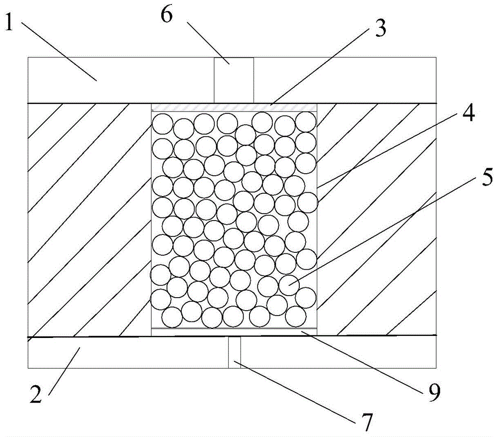
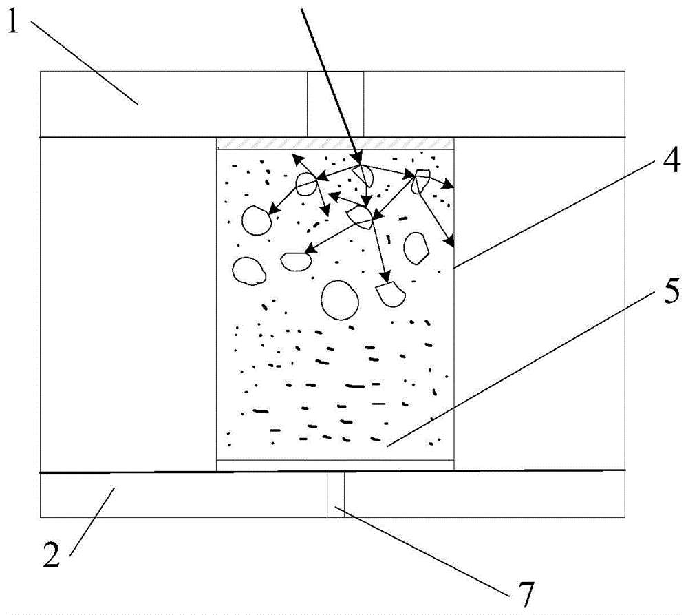
[0023] Such as figure 2 As shown, the attenuation sampling device of the present invention includes a front panel 1, an attenuation unit and a rear panel 2 arranged in sequence along the laser incident direction, the front panel 1 is processed with a sampling straight hole 6, and the rear panel 2 is provided with a laser exit hole 7 , the attenuation unit includes a front transmission window 3, a rear transmission window 9 and a cylindrical cavity 4, the front transmission window 3 is arranged close to the sampling straight hole 6, and the rear transmission window 9 is arranged close to the laser exit hole 7, The cylindrical cavity 4 is arranged coaxially with the straight sampling hole 6 and the laser exit hole 7 , and the cylindrical cavity 4 is filled with granular optical body scattering material 5 . A front transmission window 3 and a rear transmission window 9 are respectively arranged on the front and rear panels, and the two panels are stacked together so that the sam...


PUM


Abstract

The invention discloses an attenuation sampling device used for large-angle high-energy laser incidence. The device comprises a front panel, an attenuation unit and a rear panel, wherein a straight laser incidence sampling hole is formed in the front panel, a laser exiting hole is formed in the rear panel, the attenuation unit comprises a front transmission window, a rear transmission window and a cylindrical cavity, the cylindrical cavity is arranged coaxial with the straight sampling hole and the laser exiting hole, and the cylindrical cavity is filled with granular optical volume scattering materials. After being coupled into the attenuation unit through the sampling hole, absorbed through inner walls and the materials, and subjected to volume scattering, lasers are emitted out through the laser exiting hole, laser beam energy can be redistributed in a space within a wide range, and the homogenization effect is achieved; meanwhile, large-angle attenuation sampling can be achieved in the laser oblique incidence, the requirement for substantial attenuation of laser power density can be met, and the device can be used for high-spatial-resolution light intensity detection.

Description

technical field [0001] The invention relates to a method for high-energy laser large-angle measurement, in particular to a device for sampling high-energy laser large-angle attenuation by using volume scattering materials. Background technique [0002] In the measurement of high-energy laser parameters, the photodetector array sampling method is often used to obtain the temporal and spatial distribution information of laser spot power density. Since the laser power density at the test position is generally high, it is difficult to directly use the photodetector array to measure, so in the actual test, the measured laser power density needs to be reasonably attenuated to meet the range of the photodetector. scope. [0003] The far-field laser transmitted through the atmosphere usually enters the photodetector array at a certain angle. Due to the uncertainty of atmospheric transmission and the diversity of high-energy laser use, it is necessary to ensure that the photodetecto...

Claims


Application Information

Patent Timeline
Patent Type & Authority Applications(China)
IPC IPC(8): G01J1/04
Inventor 赵海川杨鹏翎吴勇陈绍武王振宝闫燕张磊陶蒙蒙武俊杰冯国斌
Owner NORTHWEST INST OF NUCLEAR TECH
Learn More