
Driving mechanism

A driving device and a driven technology, applied in installation, TV, color TV, etc., can solve problems such as narrow range, high device cost, and lower resonance frequency

Inactive Publication Date: 2006-10-04
FUJI PHOTO OPTICAL CO LTD
View PDF1 Cites 4 Cited by
  • Summary
  • Abstract
  • Description
  • Claims
  • Application Information

AI Technical Summary

Problems solved by technology

Therefore, there is a problem that the cost of the device is high
In addition, according to the conditional expression shown in this document, the range that can be set as the driving frequency is relatively narrow ( Image 6 The range of Q in (B)), therefore, there is a problem that when there is an error in the quality of the device or a failure occurs, the resonance frequency is lowered so that the condition is deviated from, thereby being affected by the resonance

Method used


Image

  • Driving mechanism
  • Driving mechanism
  • Driving mechanism

Examples


Embodiment Construction

[0050] Next, preferred embodiments of the driving device of the present invention will be described in detail with reference to the drawings. In addition, in description of drawings, the same code|symbol is attached|subjected to the same element, and repeated description is abbreviate|omitted.

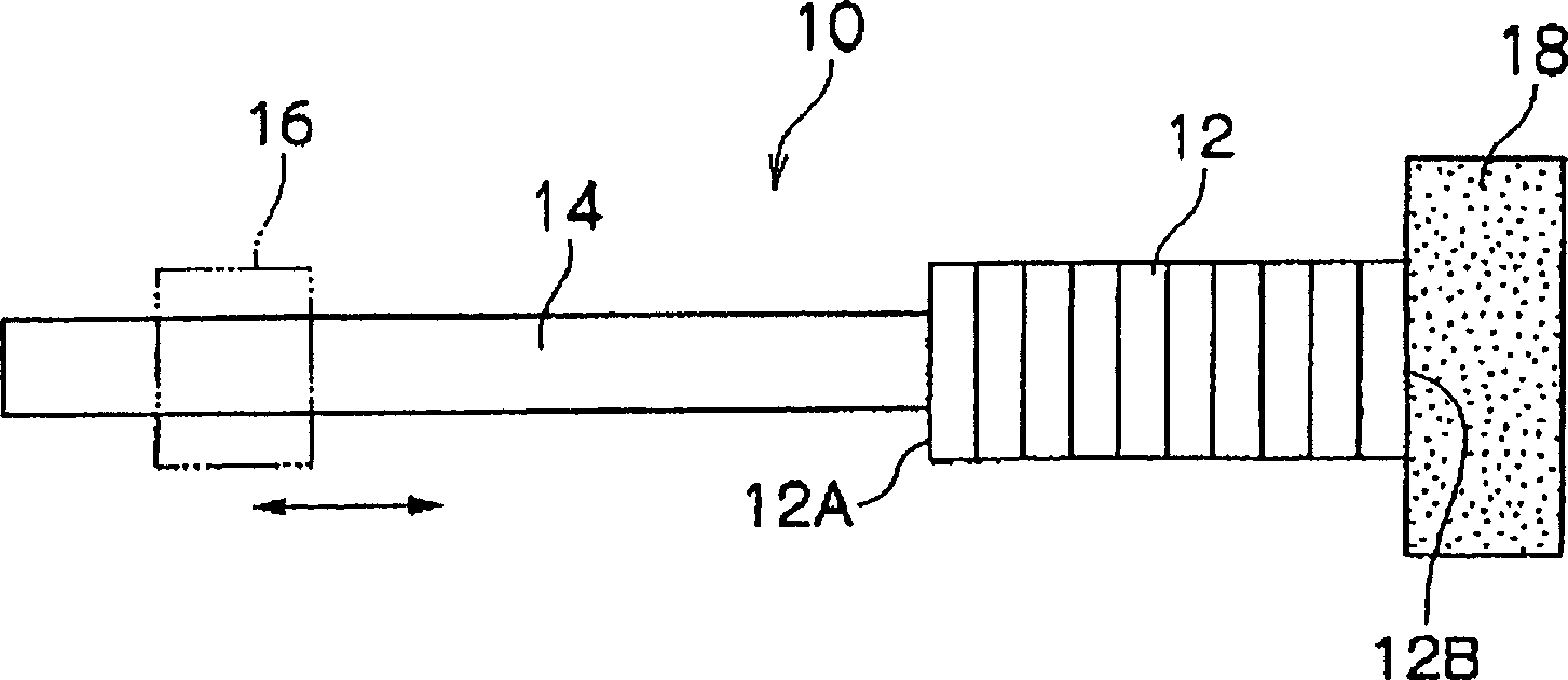
[0051] figure 1 It is a plan view showing the actuator 10 of the driving device 100 according to the first embodiment of the present invention. like figure 1 As shown, the actuator 10 is composed of a piezoelectric element (corresponding to an electromechanical conversion element) 12 , a drive member 14 , and a hammer member 18 . The piezoelectric elements 12 are stacked in the direction of the arrow, and deformed (expandable) in the stacking direction by application of a voltage. Accordingly, the end faces 12A and 12B in the longitudinal direction of the piezoelectric element 12 are displaced.

[0052] The proximal end of the driving member 14 is fixedly connected to one end sur...


PUM


Abstract

A driving mechanism comprises: (i) an actuator comprising: an electro-mechanical conversion element; a driving member which is connected to one end of the electro-mechanical conversion element and moves according to elongation or contraction of the electro-mechanical conversion element; and a weight member provided on the other end of the electro-mechanical conversion element; (ii) a driven member frictionally engaged with the driving member; and a driving circuit (26) that drives the actuator, wherein the actuator allows the driven member to move along the driving member, and the driving circuit drives the electro-mechanical conversion element at a driving frequency f which gives f 2 1 / 2 f 0 when resonance frequency of a 1-freedom system is f 0 in which the electro-mechanical conversion element and the driving member are designated as a mass and the weight member is designated as a spring, and driving frequency of the electro-mechanical conversion element is f.

Description

technical field [0001] The present invention relates to a drive device, and more particularly to a drive device for driving optical components such as relatively small lenses disposed in a compact digital camera, a network camera, or a mobile phone with a camera. Background technique [0002] As a driving device for a lens such as a digital camera, an actuator using an electric device such as a piezoelectric element to convert electric elements is known. For example, as shown in the embodiments of Patent Document 2 and Patent Document 3, the actuator is composed of an electromechanical conversion element and a driving part, and generally the end face of the electromechanical conversion element in one direction of expansion and contraction is fixed to the casing (or the support member). )superior. The driving part is fixed on the end face of the electromechanical conversion element in the other direction of expansion and contraction, and the driving part is frictionally comb...

Claims


Application Information

Patent Timeline
Patent Type & Authority Applications(China)
IPC IPC(8): G02B7/02H01L41/00H04N5/225
Inventor 真锅充雄一宫武史
Owner FUJI PHOTO OPTICAL CO LTD
Learn More