
Resonance measuring chucking appliance of hard disk drive rack

A resonance measurement, hard disk drive technology, applied in measurement devices, ultrasonic/sonic/infrasonic waves, instruments, etc., can solve the problems of inaccurate measurement results, large differences in measurement results, and inability to more realistically reproduce the vibration characteristics of the drive frame. , to achieve the effect of ensuring accuracy

Active Publication Date: 2009-04-15
福群科技(东莞)有限公司
View PDF0 Cites 5 Cited by
  • Summary
  • Abstract
  • Description
  • Claims
  • Application Information

AI Technical Summary

Problems solved by technology

However, the test environment simulated by the current resonance measurement fixture is often quite different from the actual working environment of the hard disk, and cannot truly reproduce the vibration characteristics of the drive frame in the actual working environment, so that different resonance measurement fixtures are selected. The measurement results Often vary widely and measurements are inaccurate

Method used


Image

  • Resonance measuring chucking appliance of hard disk drive rack
  • Resonance measuring chucking appliance of hard disk drive rack
  • Resonance measuring chucking appliance of hard disk drive rack

Examples


Embodiment 1

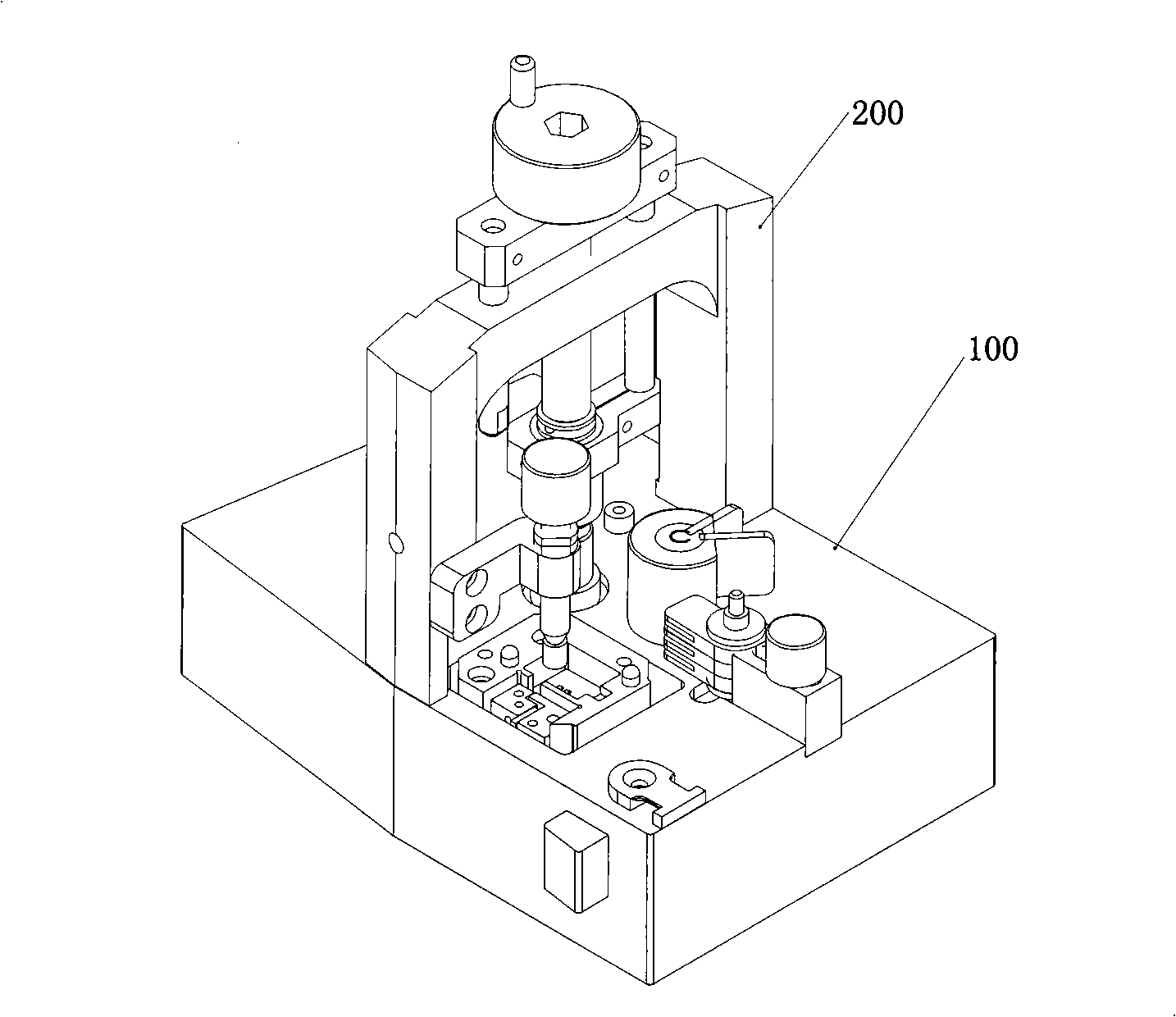
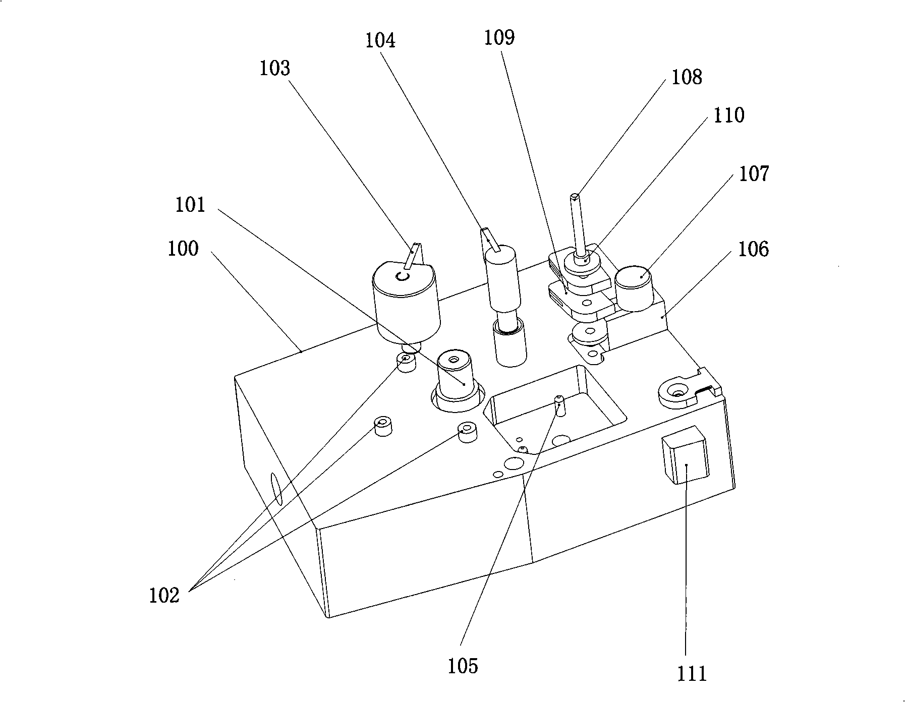
[0026] One surface of the base 100 is provided with a drive frame support column 101 for placing the drive frame. The drive frame support column 101 is generally located in the center of the plane, and can also be located near the center of the plane, or in other positions on the plane.

[0027] A magnet support column 102 is provided around the driving frame support column 101. Generally, about three magnet support columns 102 can be provided to better support the magnet. The drive frame support column 101 is higher than the magnet support column 102 by a set value. The set value is set according to different products, so that the magnet placed on the two has a certain height difference with the drive frame. To ensure that the height difference between the magnet and the excitation coil of the drive frame is 0.5 to 1.0 mm. This height dimension is the height dimension used by the analog drive frame during the actual use of the hard disk. This height dimension will vary according ...

Embodiment 2

[0033] This embodiment is based on the first embodiment. In this embodiment, drive frame positioning posts 103 and 104 are also provided around the drive frame support column 101. The drive frame positioning posts 103 and 104 are used to locate the position of the drive frame to ensure different In different measurement processes, the position of the drive frame is consistent, which improves the accuracy of the measurement results and the repeatability of the measurement process.

Embodiment 3

[0035] This embodiment is based on the first and second embodiments. In the present invention, in some cases, the drive frame is additionally connected with a cable piece and / or a magnetic head. When the drive frame is also connected with a cable piece or a magnetic head, corresponding positioning components need to be provided on the base 100.

[0036] When the drive frame is further connected with a cable sheet, in this embodiment, a groove is also provided around the drive frame support column 101, and a cable sheet positioning post 105 is provided in the groove to position the cable sheet.

[0037] When the drive frame is also connected to the sub-head, in this embodiment, a sub-head positioning assembly is also provided around the drive frame support column 101, and the sub-head positioning assembly includes a slider 106 that can move in the chute. A slider nut 107 that can lock the slider 106 above the slider 106, a post 108 on one side of the slider 106, a sub-head position...


PUM


Abstract

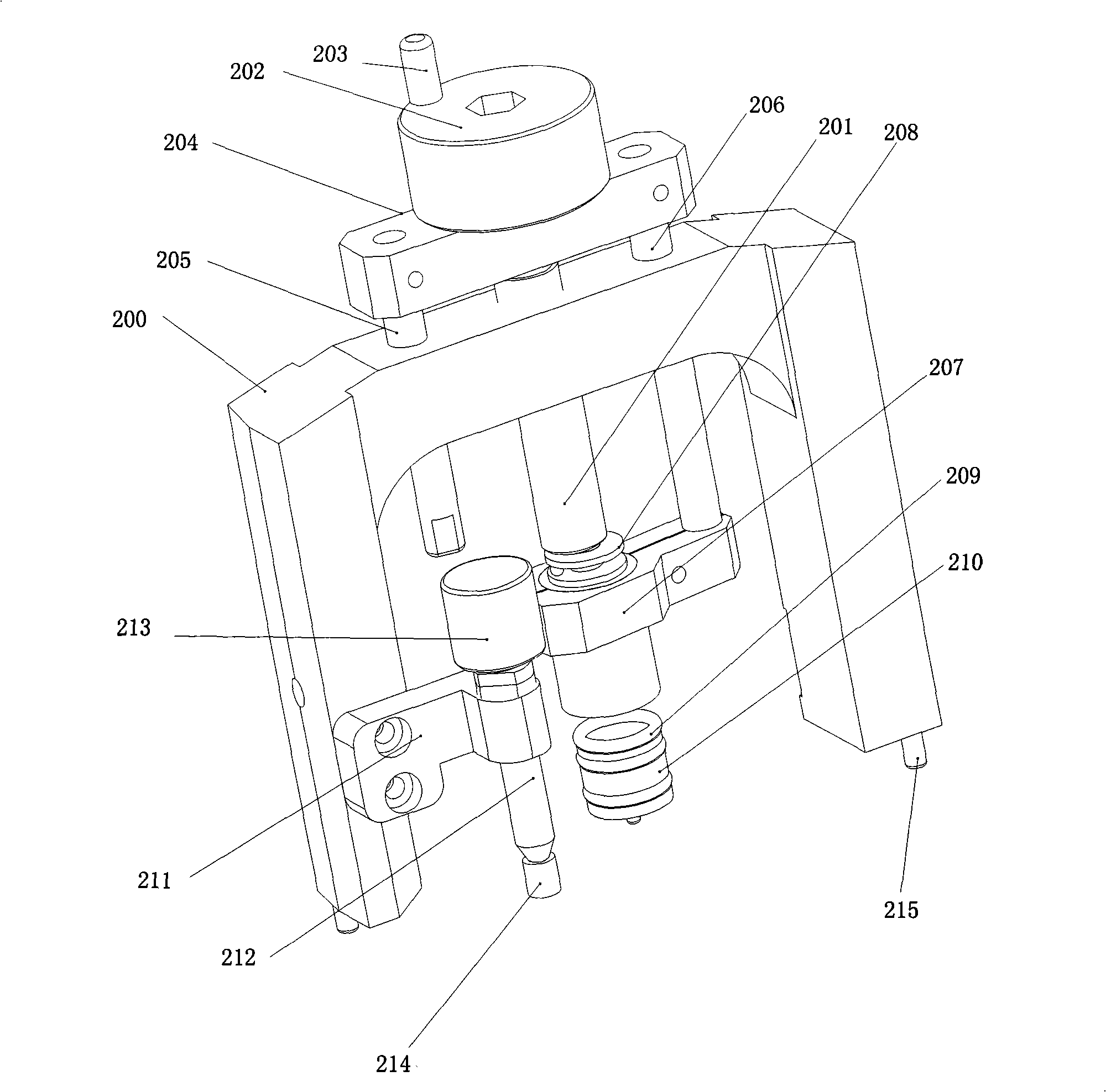
The invention discloses a resonance measuring clamp of a hard-disk drive frame. The resonance measuring clamp comprises a substrate and a portal frame; one surface of the substrate is provided with a prop of the drive frame used for placing the drive frame, magnet props are arranged around the prop of the drive frame, and the ratio between the drive frame prop the magnet prop is higher than the set value; the surface with the prop of the drive frame of the substrate and the surface that is opposite with the surface with the prop of the drive frame are the planes; the mass of the substrate is over 100 times than the mass of the drive frame; the portal frame is vertically fixed on the plane with the prop of the drive frame of the substrate, and a lockout module used for locking the drive frame is arranged right above the prop of the drive frame. The resonance measuring clamp of the invention simulates the situation that the drive frame is used in the real hard-disk using process, thus measuring the resonance characteristic of the product more accurately; meanwhile, the mass of the measuring clamp is far heavier than the mass of the drive frame, so that the influence on the resonance of the drive frame caused by the measuring clamp is little, and the accuracy of the measuring result can be ensured.

Description

【Technical Field】 [0001] The invention relates to the technical field of drive frame testing, in particular to a resonance measurement fixture of a hard disk drive frame. 【Background technique】 [0002] As the storage density of hard disks continues to increase and the speed of reading and writing increases rapidly, the vibration characteristics of the drive frame in the hard disk are increasingly required. Therefore, it is increasingly important to accurately measure the vibration characteristics of the hard disk drive frame. [0003] At present, there are many methods for measuring the vibration characteristics of the hard disk drive frame, and the drive frame generally needs to be fixed. There are also many structures of resonance measurement jigs used to fix the drive frame. However, the test environment simulated by the current resonance measurement fixture is often quite different from the actual working environment of the hard disk, and cannot truly reproduce the vibration...

Claims


Application Information

Patent Timeline
Patent Type & Authority Applications(China)
IPC IPC(8): G01H9/00
Inventor 徐晓静叶权黎治易黄若辰陈珏然
Owner 福群科技(东莞)有限公司
Learn More