Beam shaping method for inhibiting interferes

一种波束赋形方法、干扰抑制的技术,应用在多个站之间的通信、无线电传输系统、电气元件等方向,能够解决增加干扰信号估计误差的敏感度、赋形波束方向性偏离、功率下降等问题,达到抑制强干扰、控制干扰功率小的效果

Active Publication Date: 2006-11-01
SHANGHAI ULTIMATE POWER COMM TECH
View PDF0 Cites 13 Cited by
  • Summary
  • Abstract
  • Description
  • Claims
  • Application Information

AI Technical Summary

Problems solved by technology

In addition, it is impossible for the desired signal and the interference signal to be completely orthogonal. From this point of view, there is a certain contradiction between the maximization of the desired signal and the zeroing of the interference signal. Shaped Beam Directional Deviation
[0008] It can be seen that due to the limitation of degrees of freedom and orthogonality, the beamforming algorithm based on the maximum carrier-to-interference ratio criterion is difficult to guarantee the direction of the main lobe of the beam and the power of the desired signal, which not only causes a decrease in power, but also increases the estimation of interference signals. Sensitivity to error

Method used


Image

  • Beam shaping method for inhibiting interferes
  • Beam shaping method for inhibiting interferes
  • Beam shaping method for inhibiting interferes

Examples


Embodiment Construction

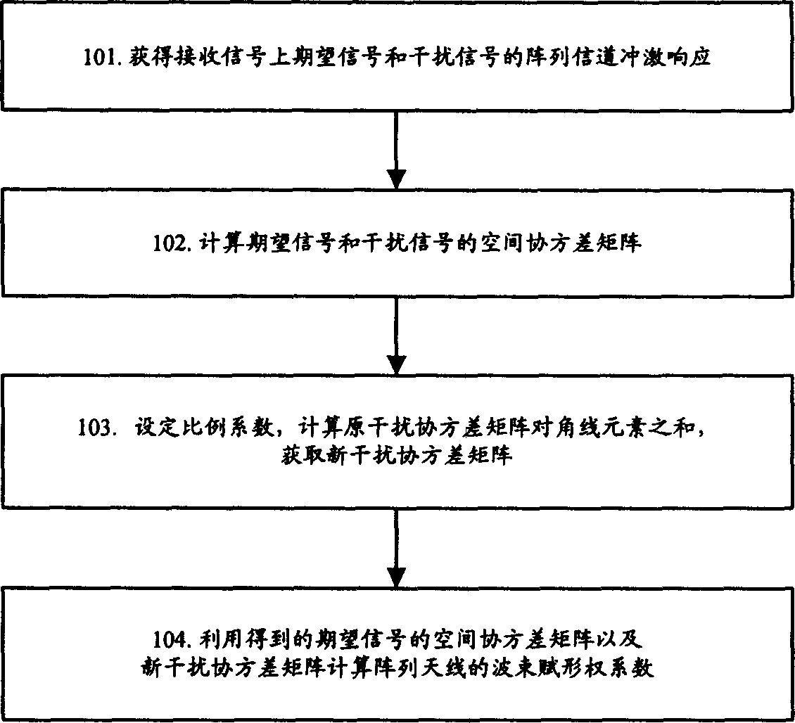
[0026] Because in the beamforming algorithm of the maximum carrier-to-interference ratio criterion, it is generally necessary to maximize the received signal-interference & noise ratio (SINR, Signal-Interference & Noise Ratio) of the desired user signal. In other words, the formula ( 1) The covariance matrix in the denominator is the sum of the interference covariance matrix and the noise covariance matrix, and because noise has no spatial correlation characteristics, the spatial covariance matrix of the noise is the identity matrix. Let the covariance matrix in the denominator of formula (1) be the sum of the interference covariance matrix and the noise covariance matrix. It is feasible when receiving beamforming, but in the transmission process, because the noise sequence received by the user is fixed, so There is no noise covariance matrix in the transmission process, only interference covariance matrix.

[0027] For the beamforming algorithm, only by simultaneously suppressing...


PUM


Abstract

The method comprises: a) respectively making channel estimation for the expected signal and the interference signal in those signals received from current antenna array to get the channel array impulse responses respectively corresponding to the expected signal and the interference signal; b) in term of obtained channel impulse response, calculating its own space covariance matrix of either the expected signal or the interference signal; c) in term of the relation between the expected signal and interference signal, getting a new interference signal space covariance matrix; d) in term of the expected signal space covariance matrix and the new interference signal space covariance matrix, calculating beam-forming weight coefficient of current antenna array.

Description

Technical field [0001] The present invention relates to beamforming technology, in particular to an interference suppression beamforming method that guarantees user directionality. Background technique [0002] The so-called beamforming refers to the process of calculating the optimal weight vector according to the parameters, specifically: the process of realizing the optimal (sub-optimal) combination or optimal (sub-optimal) allocation of signals according to the measured and estimated parameters. The beamforming technology uses an antenna array to gather the signal energy into a very narrow beam, which improves the propagation efficiency of the antenna, the reliability of the wireless link and the frequency reuse rate. The beamforming algorithm can be designed based on different criteria. Generally speaking, the criteria on which the beamforming algorithm is based include two categories: user-based maximum power criteria and user-based maximum carrier-to-interference ratio cri...

Claims


Application Information

Patent Timeline
Patent Type & Authority Applications(China)
IPC IPC(8): H04B7/26H01Q3/26H01Q21/00
CPCH04B7/0854H04B7/086
Inventor 孙长果杨贵亮王映民
Owner SHANGHAI ULTIMATE POWER COMM TECH
Why Eureka
Try Eureka