Crossbeam support pole mechanism

A technology for supporting columns and beams, applied in the direction of pillars, columns, pier columns, etc., can solve the problems of high cost, labor and time, and achieve the effects of low cost, convenient installation and disassembly operations, and flexible and convenient use

Inactive Publication Date: 2006-11-08
李博
View PDF0 Cites 2 Cited by
  • Summary
  • Abstract
  • Description
  • Claims
  • Application Information

AI Technical Summary

Problems solved by technology

The disadvantages of using this kind of beam support column mechanism are labor-intensive, time-consuming, wood-consuming, high cost, and cumbersome operating procedures

Method used


Image

  • Crossbeam support pole mechanism
  • Crossbeam support pole mechanism
  • Crossbeam support pole mechanism

Examples


Embodiment Construction

[0010] The present invention will be further described in detail below in conjunction with the accompanying drawings and embodiments.

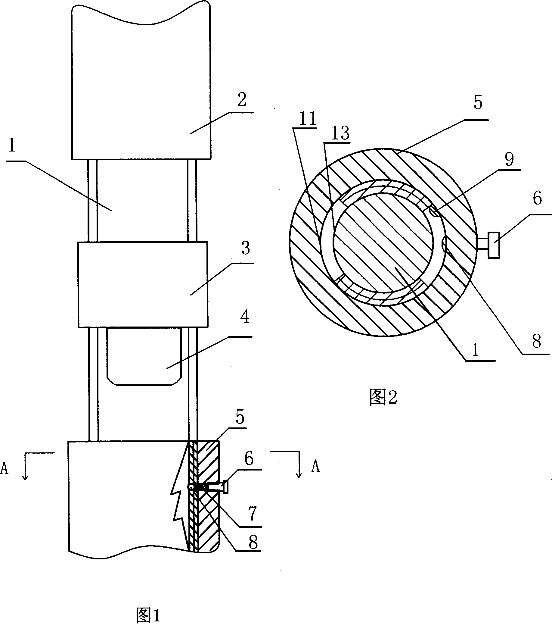
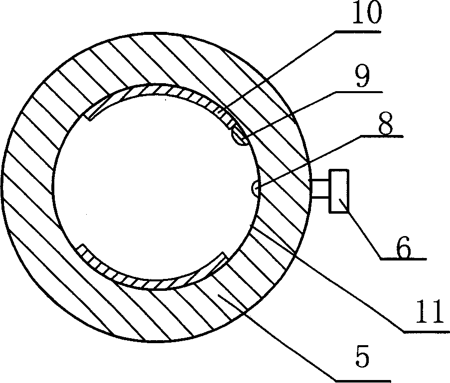
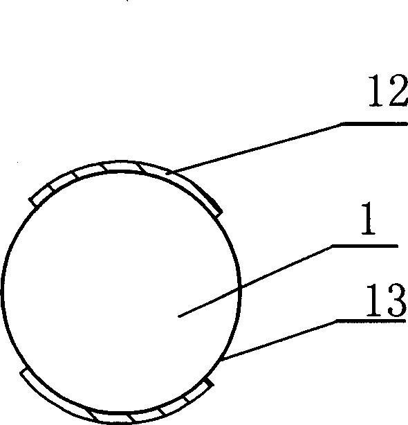
[0011] A beam support column mechanism, as shown in Figure 1 and Figure 2, which includes a screw 1 and a fine-tuning nut 2 on the top; the screw 1 and the fine-tuning nut 2 are threaded in a common way; the bottom of the screw 1 is installed in a common way The slidable nut 5; the fine-tuning nut 2 is connected with a common metal rod, and the fine-tuning nut 2 is integrated with the metal rod; Overall; in this example, such as image 3 , Figure 4 As shown, the external thread 12 on the screw 1 is divided into two sections in the circumferential direction, and the slidable nut 5 has two internal threads 10 corresponding to the external thread 12 on the screw 1; the screw 1 is covered with The backstop sleeve 3 is common, and the backstop sleeve 3 is located between the fine-tuning nut 2 and the slidable nut 5; Corresponding to the cylindri...


PUM


Abstract

The present invention discloses a kind of low cost crossbeam supporting column mechanism with screws and trimming nuts. The low cost crossbeam supporting column mechanism possesses telescoping function, trimming function and self locking function. It has easy assembling and disassembling, flexible use and low cost.

Description

technical field [0001] The invention relates to the construction field, in particular to a beam support column structure used in the construction. Background technique [0002] At present, the known beam support column mechanism mainly adopts logs or wooden strips. In the specific work, first cut the logs or wooden strips into a certain size and bind them into T-shaped support columns, and then put the T-shaped support columns under the already erected formwork to withstand the formwork. If the T-shaped support column is too high, it needs to be sawed shorter, and if it is too short, it is necessary to fill in bricks and wedges under the T-shaped support column. The disadvantages of using this kind of beam support column mechanism are labor-intensive, time-consuming, wood-consuming, high cost, and cumbersome operating procedures. Contents of the invention [0003] The object of the present invention is to provide a low-...

Claims


Application Information

Patent Timeline
Patent Type & Authority Applications(China)
IPC IPC(8): E04C3/30
Inventor 李博
Owner 李博
Why Eureka
Try Eureka