Mixing machine for engineering plastic modification

A technology of engineering plastics and mixers, which is used in drying solid materials, cleaning methods and utensils, drying solid materials without heating, etc. High tide efficiency

Inactive Publication Date: 2020-06-30
邹晓雪
View PDF5 Cites 6 Cited by
  • Summary
  • Abstract
  • Description
  • Claims
  • Application Information

AI Technical Summary

Problems solved by technology

[0003] The purpose of the present invention is to provide a mixer for engineering plastics modification, to solve the problem of environmental deliquescence before mixing, a large amount of water droplets attached to the inner wall of the mixing cylinder, when making plastic solid / solid mixing Due to the limitation of the diameter of the barrel mouth, it is difficult for the user to fully remove the water on the barrel wall, resulting in uneven mixing, which will cause obvious cracks, material flakes, and even technical problems on the surface of the post-processed product.

Method used


Image

  • Mixing machine for engineering plastic modification
  • Mixing machine for engineering plastic modification
  • Mixing machine for engineering plastic modification

Examples


Embodiment 1

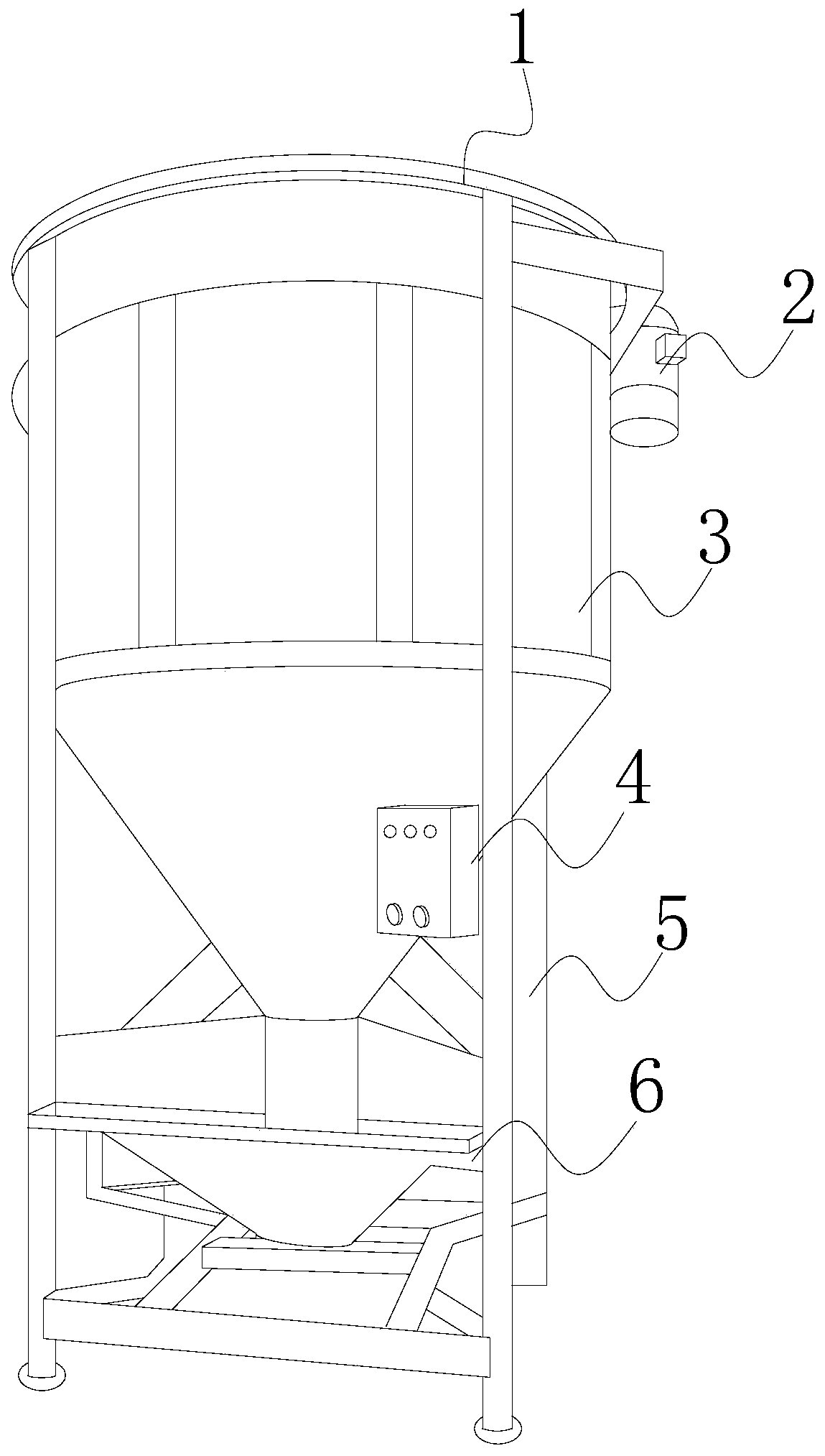
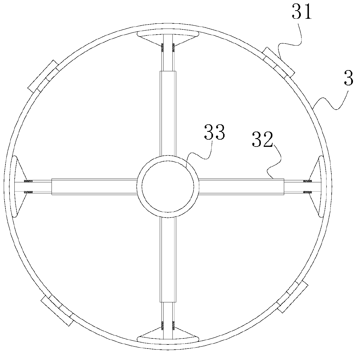
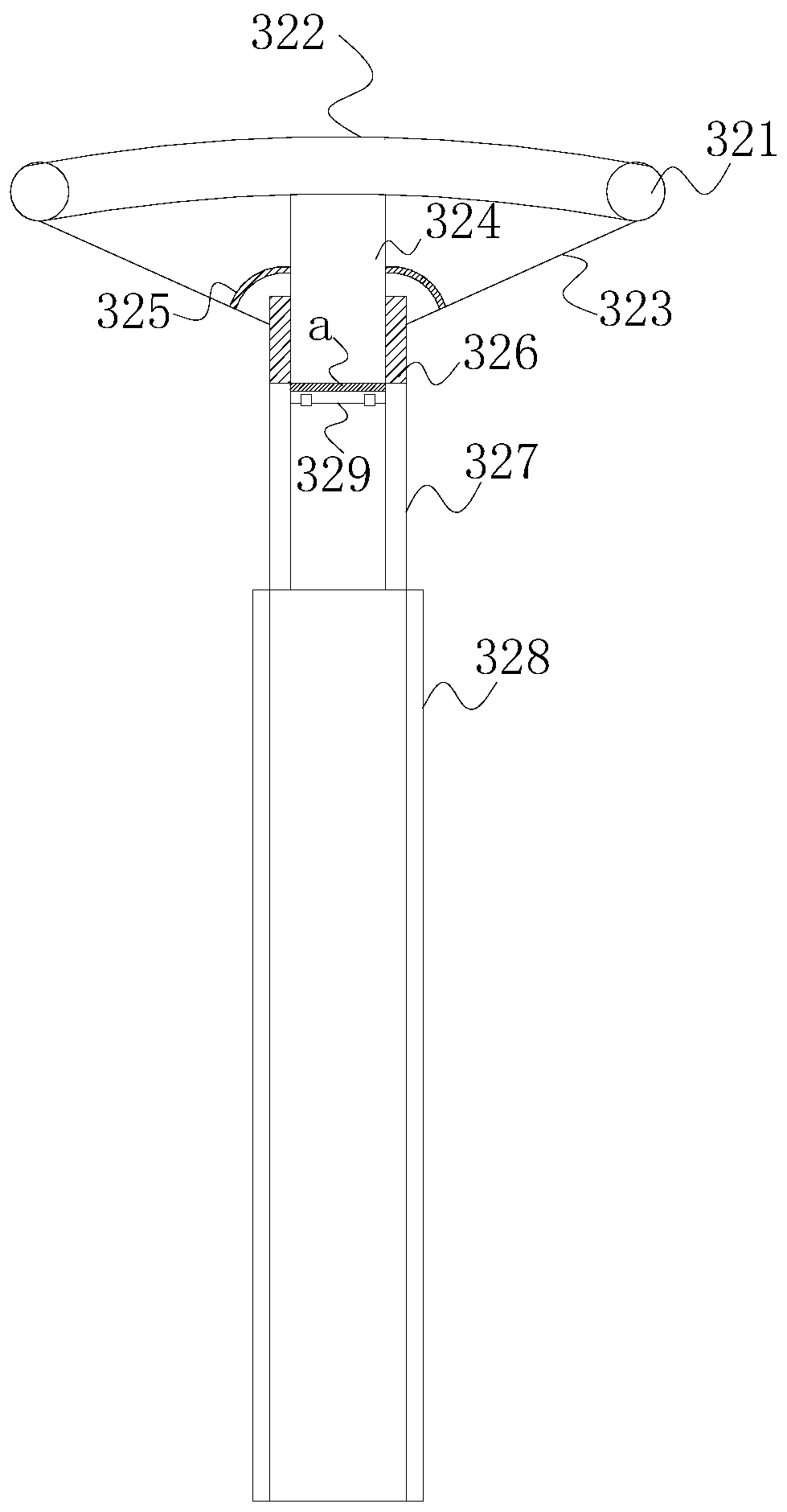
[0027] Such as Figure 1-Figure 4 As shown, the present invention provides a mixer for modification of engineering plastics, and its structure includes a top cover 1, a motor 2, a mixing cylinder 3, an operating cabinet 4, a support frame 5, and a discharge chassis 6. The top cover 1 Installed on the upper end of the mixing cylinder 3, the rotating shaft 33 inside the mixing cylinder 3 is driven by the motor 2, the operating cabinet 4 controls the motor 2, the bottom of the mixing cylinder 3 and the discharge chassis 6 are internally connected and welded together, The support frame 5 is mechanically connected to the outer surface of the mixing cylinder 3 and the discharge chassis 6, and the inside of the mixing cylinder 3 is provided with a chuck 31, a telescopic stirring shaft 32, and a rotating shaft 33, and the chuck 31 is provided with four, It is evenly distributed on the outside of the mixing cylinder 3 in a circle, and the telescopic stirring shaft 32 is provided with f...

Embodiment 2

[0029] Such as Figure 5 As shown, based on Example 1, the telescopic plastic tube is used to scrape off the water on the cylinder wall before mixing, so as to avoid the humidity inside the mixing cylinder, and solve the problem of difficult moisture removal on the cylinder wall. The sealing piston changes the pressure inside the telescopic plastic tube On the basis of making the telescopic plastic tube fuller when opened and having higher moisture removal efficiency, the chuck 31 includes a fixed frame 311, a propeller 312, a mounting groove 313, and a movable sealing plate 314 through the mutual cooperation of the following structural components , a liquid outlet hole 315, a liquid contact layer 316, a propeller 312 is installed inside the fixed frame 311, and the propeller 312 is respectively arranged on both sides of the installation groove 313 and connected with the movable sealing plate 314, and the movable sealing plate A liquid contact layer 316 is arranged between the...


PUM


Abstract

The invention discloses a mixing machine for engineering plastic modification. The mixing machine structurally comprises a top cover, a motor, a mixing drum, an operation case, a support frame and a discharging base plate, wherein the top cover is arranged at the upper end of the mixing drum; a rotating shaft inside the mixing drum is driven by the motor; the operation case controls the motor; thebottom of the mixing drum and the discharging base plate internally communicate with each other and are welded together; the support frame is mechanically coupled to the outer surfaces of the mixingdrum and the discharging base plate; and four chucks, telescopic stirring shafts and the rotating shaft are arranged inside the mixing drum. According to the mixing machine, through the combined action of inner telescopic rods, outer fixing rods, sliding blocks and walking devices, when the telescopic stirring shafts with the telescopic function are opened, auxiliary expansion wheels open telescopic plastic tubes to make full contact with the wall of the mixing drum, the telescopic plastic tubes are used for scraping the water on the drum wall before mixing, the humid environment in the mixingdrum is avoided, and a problem of difficulty in dehumidification of the drum wall is solved.

Description

technical field [0001] The invention relates to the field of plastic processing, in particular to a mixer for engineering plastic modification. Background technique [0002] During the manufacturing process of engineering plastics, it is sometimes necessary to mix various engineering plastics together to prepare modified mixed engineering plastics. This modified engineering plastics needs to be mixed with a mixer. During preparation, these Engineering plastics are added to the mixer. There is a special mixing cylinder combined with a stirring system in the mixer to make the mixing more complete. However, the existing mixing cylinder is made of stainless steel. Before mixing, it is affected by the deliquescence of the environment. There are a lot of water droplets attached to the inner wall. When making plastic solid / solid mixing, it is difficult for the user to fully remove the water on the cylinder wall due to the limitation of the diameter of the cylinder mouth, resulting ...

Claims


Application Information

Patent Timeline
Patent Type & Authority Applications(China)
IPC IPC(8): B29B7/16B29B7/22F26B5/14F26B5/16B08B9/087
CPCB08B9/087B29B7/16B29B7/22F26B5/14F26B5/16
Inventor 邹晓雪
Owner 邹晓雪
Why Eureka
Try Eureka