
Identification system for defibrillator electrode package

A technology of electrode assembly and defibrillator, applied in the direction of cardiac defibrillator, electrode, electrotherapy, etc.

Active Publication Date: 2006-11-08
KONINKLIJKE PHILIPS ELECTRONICS NV
View PDF1 Cites 6 Cited by
  • Summary
  • Abstract
  • Description
  • Claims
  • Application Information

AI Technical Summary

Problems solved by technology

[0006] The problem addressed by the present invention is therefore to develop a method and apparatus to enable an automatic external defibrillator to operate in the correct operating mode without increasing its size, weight, or complexity

Method used


Image

  • Identification system for defibrillator electrode package
  • Identification system for defibrillator electrode package
  • Identification system for defibrillator electrode package

Examples


Embodiment Construction

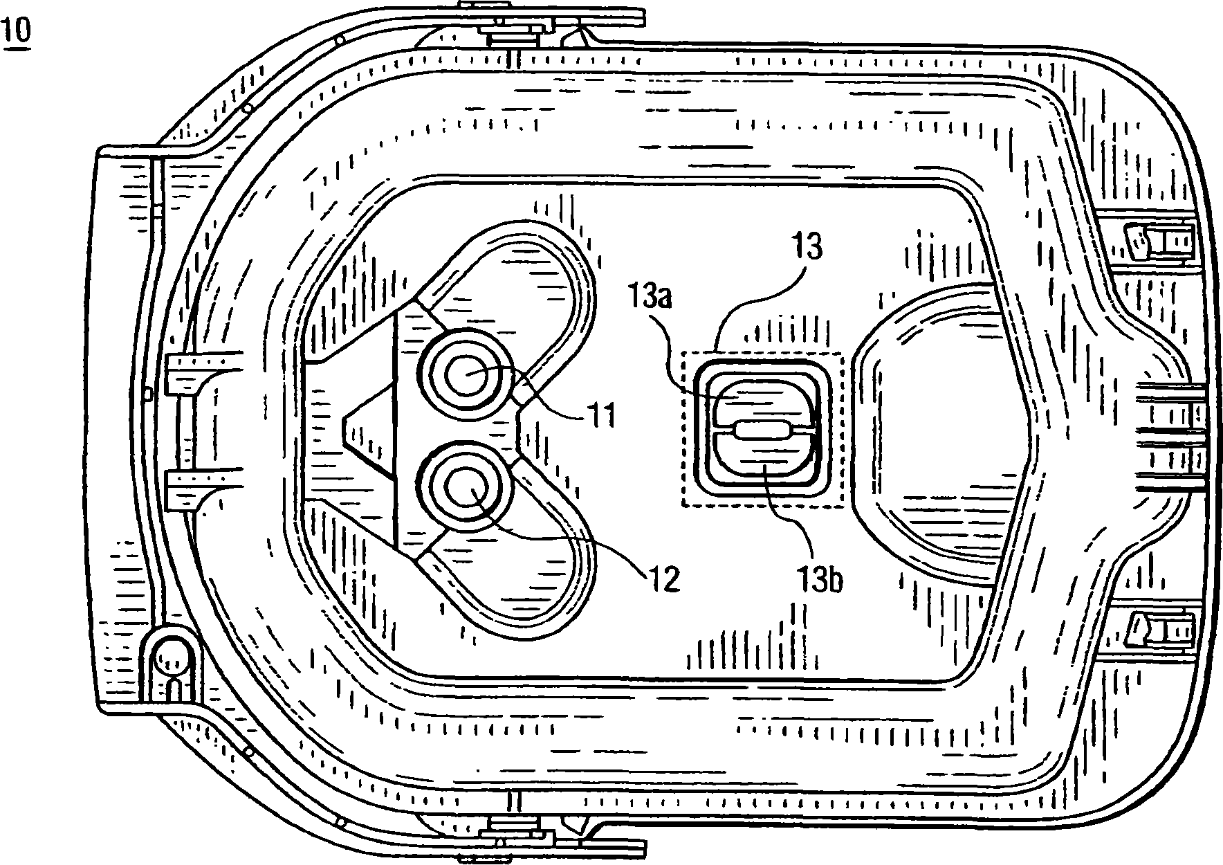
[0018] exist figure 1 In the illustrated embodiment 10, a shaped conductive label 13 having two parts 13a, 13b is placed on the back of the rigid electrode cartridge 10. Contacts 11 and 12 are power contacts through which current or ECG signals flow when the electrodes are in use (assuming, of course, that mode of operation requires current or ECG signals). These electrodes (not shown) are stored within the unit 10 and are connected through the case wall to a defibrillator (not shown). The electrode connecting pieces 11, 12 are separated from the conductive label 13.

[0019] When the box 10 is loaded into the defibrillator seat (see element 40, Figure 4 ), the two parts 13a, 13b of the conductive label 13 and the four spring-loaded pins protruding from the seat 40 (see Figure 4 The middle element 42) is in electrical contact. In this embodiment 40, the top two pins 42b and 42d are in contact with the portion 13b of the conductive tag 13, and the bottom two pins 42a and ...


PUM


Abstract

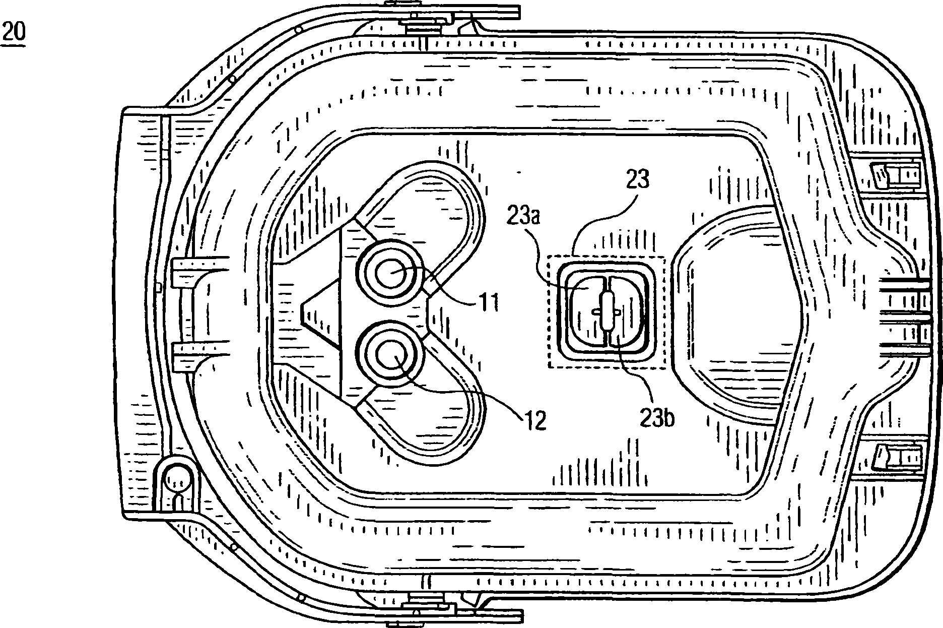
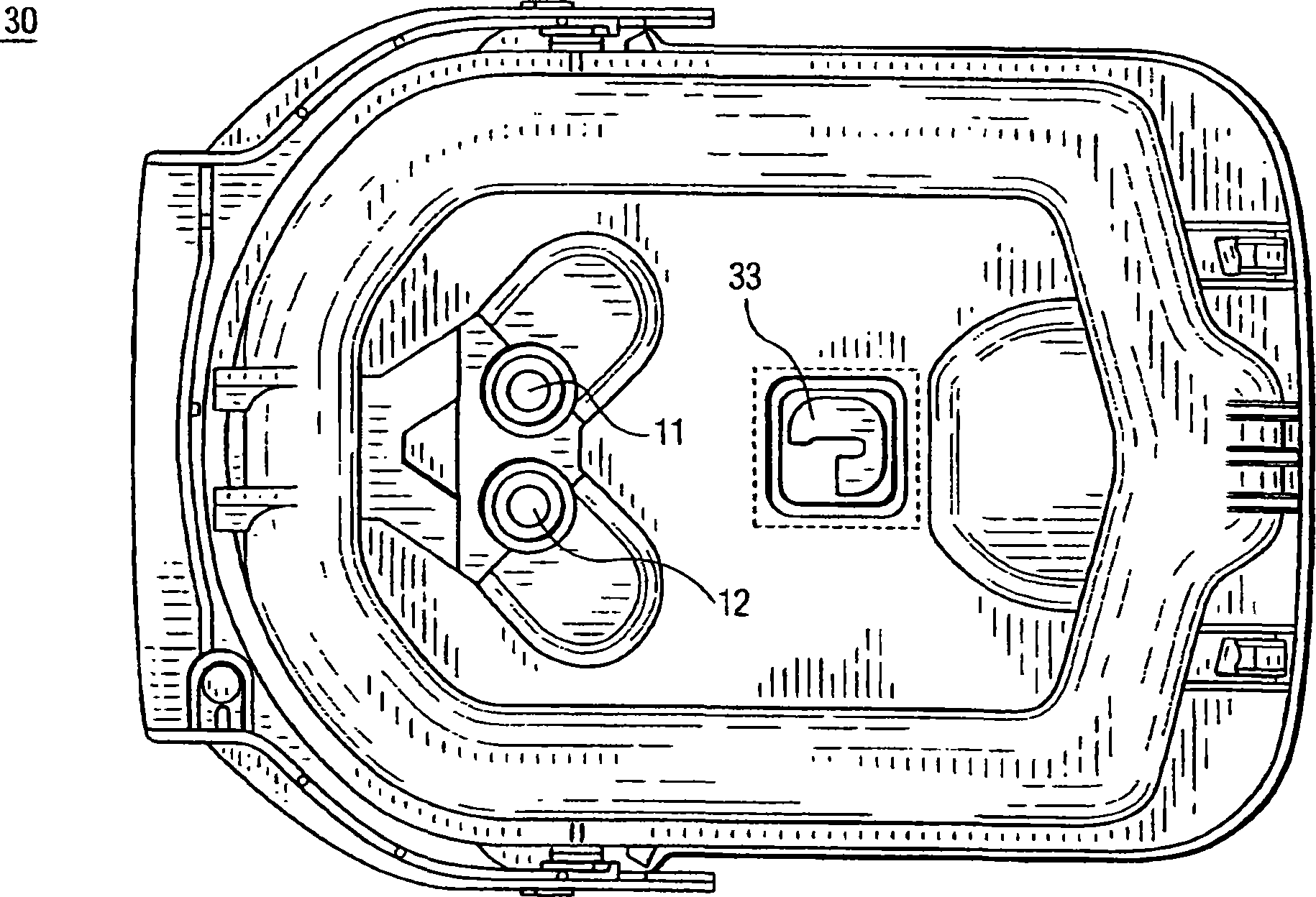
An automatic external defibrillator electrode package (10; 20; 30) includes a coded conductive label (13; 23; 33) that uniquely identifies the type of automatic electrode contained therein. Pins (42a-d) on the defibrillator body (40) make electrical contact with the conductive label (13; 23; 33) when the package (10; 20; 30) is attached to the defibrillator (50). These pins (42a-d) sense the shape of the conductive label (13; 23; 33) to ascertain the electrode type, thereby enabling the AED (50) to automatically set the proper operating mode.

Description

technical field [0001] This invention relates generally to automatic external defibrillators, and more particularly to methods and apparatus for connecting electrodes to automatic external defibrillators. Background technique [0002] Today's automatic external defibrillators (AEDs) must operate according to the mode of use. For example, an AED may be used to defibrillate an adult or an infant, each requiring a different treatment protocol. Additionally, the AED can be used in a training mode or strictly in a multi-electrode monitoring mode, where the electrodes do not deliver defibrillation energy. Thus, an AED must employ some method to determine the operating mode. [0003] There are currently several ways to switch operating modes for AEDs. One way is through manual conversion. At this point the AED user simply flips the switch to the correct mode. Manual switching represents a sub-optimal solution, since setting the manual switch requires the user (who may be using...

Claims


Application Information

Patent Timeline
Patent Type & Authority Applications(China)
IPC IPC(8): A61N1/39A61B19/00A61B19/02A61N1/04
CPCA61N1/046A61N1/0472A61N1/0492A61N1/3925A61B50/30A61B90/98A61N1/3904
Inventor E·约恩森
Owner KONINKLIJKE PHILIPS ELECTRONICS NV
Learn More