Flow channel switching valve and shower system

A flow channel switching and flow channel technology, which is applied in the field of flow channel switching valve and shower system, can solve the problem of not being able to install the shower system, etc.

Inactive Publication Date: 2006-11-08
MYM CORP
View PDF2 Cites 8 Cited by
  • Summary
  • Abstract
  • Description
  • Claims
  • Application Information

AI Technical Summary

Problems solved by technology

Thereby, under the situation that the space of bathtub i

Method used


Image

  • Flow channel switching valve and shower system
  • Flow channel switching valve and shower system
  • Flow channel switching valve and shower system

Examples


Embodiment Construction

[0028] Next, a first embodiment of the present invention will be described with reference to the drawings.

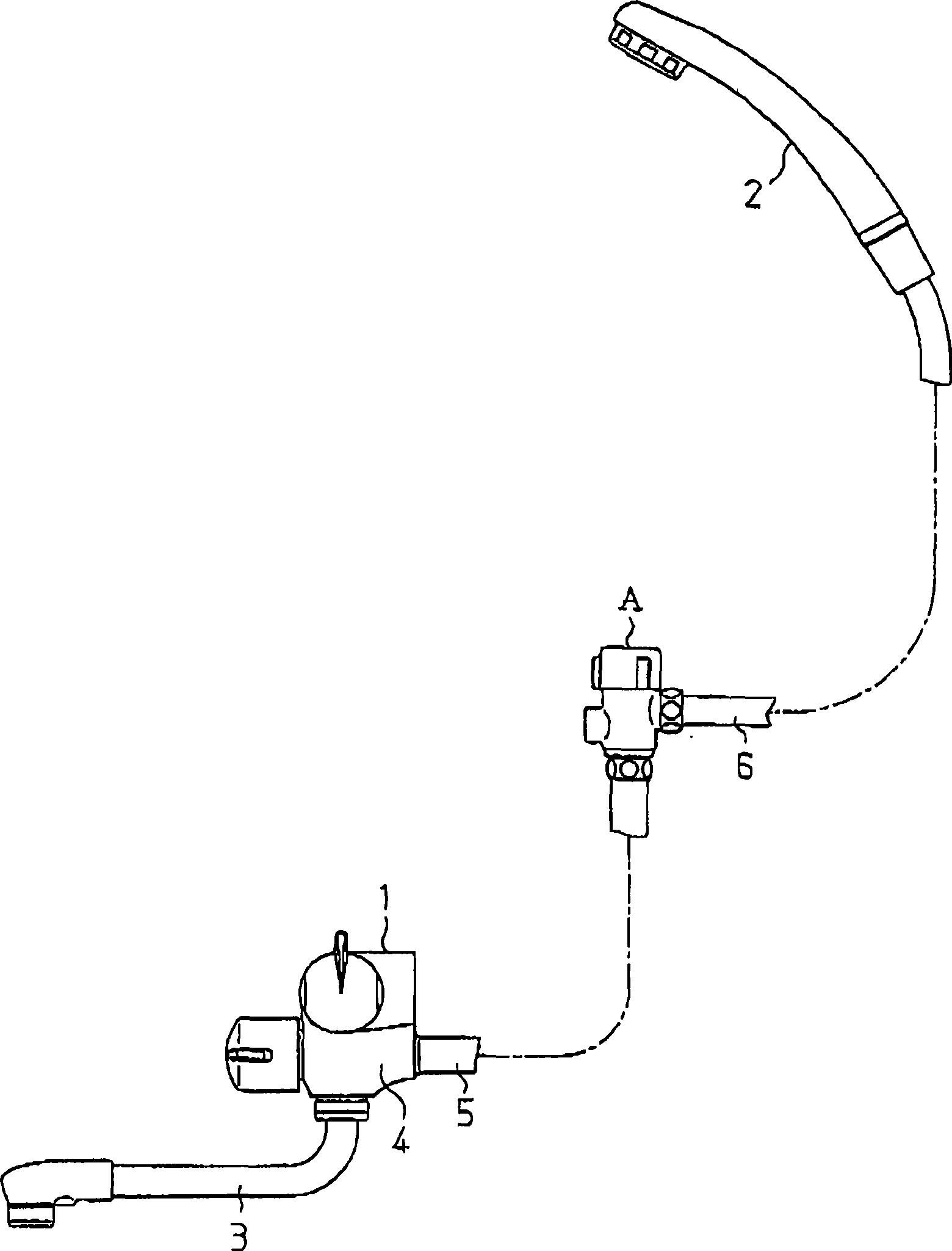
[0029] Such as figure 1 As shown, the channel switching valve A of this embodiment is installed, for example, between the mixer tap 1 and the shower head 2 in the bathroom. A supply pipe 5 is connected to the mixing faucet 1 for adjusting the temperature and flow rate of water as a fluid. The mixing faucet 1 has a switching valve 4 , and the water whose temperature and flow rate have been adjusted is selectively supplied to any one of the water supply pipe 5 and the water outlet pipe 3 of the mixing faucet 1 through the operation of the switching valve 4 . The supply pipe 5 communicates with the hose 6 through the channel switching valve A. As shown in FIG. A shower head 2 is installed at the end of the hose 6 . The channel switching valve A, the shower head 2, and the hose 6 constitute a shower system.

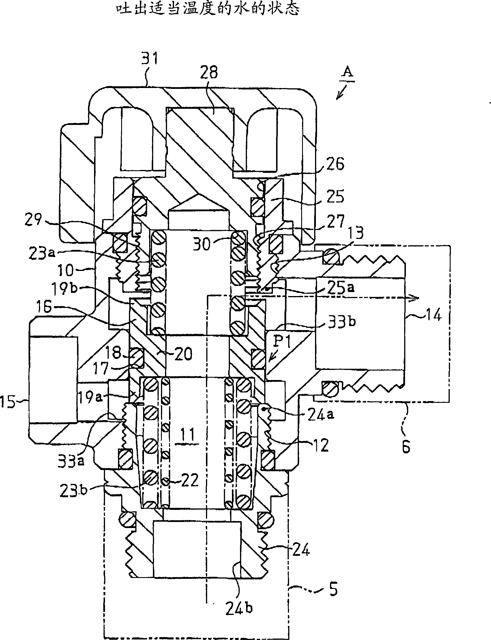
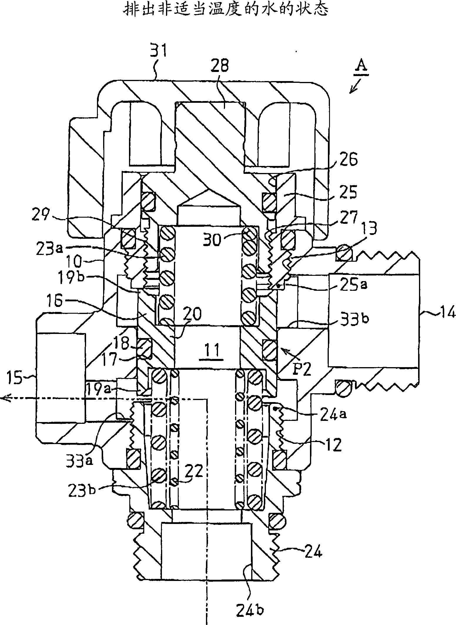
[0030] Such as figure 2 As shown, the channel switching val...


PUM


Abstract

A channel switching valve (A) of the present invention includes a discharge hole (14) which discharges water having a proper temperature and a drain hole (15) which drains water having an improper temperature. A part of a first channel (11) extending from a hot water supply port (24b) to the discharge hole and a part of a second channel (11) extending from the hot water supply port to the drain hole are common. Therefore, the channel switching valve can be compact.

Description

technical field [0001] The invention relates to a channel switching valve and a shower system. Background technique [0002] Conventionally, as a channel switching valve, for example, a configuration disclosed in Patent Document 1 is known. The channel switching valve includes: a temperature-sensing spring whose shape reversibly changes according to the temperature of the fluid flowing into the channel switching valve; and a valve core which is urged by the temperature-sensing spring. When a load is applied to the spool along with the change in shape of the temperature-sensitive spring, the spool moves in such a manner as to switch between two states, that is, a state in which the discharge port of the fluid at an appropriate temperature communicates with the flow path, so The proper temperature fluid is a fluid whose temperature is within a prescribed temperature range; and the state in which the discharge port communicates with the flow path for an unsuitable temperature ...

Claims


Application Information

Patent Timeline
IPC IPC(8): F16K31/70A47K3/28E03C1/044
Inventor 长野聪之进藤孝彦加纳忍
Owner MYM CORP
Why Eureka
Try Eureka