Method and apparatus for controllably compensating for distortions in a laser projection display

A technology of laser projection and laser, which is applied in the direction of image reproducer, picture reproducer, instrument, etc. of projection device, which can solve problems such as cumbersome optical system, distortion of rectangular image, and complex problems.

Inactive Publication Date: 2007-01-31
SYMBOL TECH INC
View PDF0 Cites 3 Cited by
  • Summary
  • Abstract
  • Description
  • Claims
  • Application Information

AI Technical Summary

Problems solved by technology

Likewise, a rectangular image projected onto a surface will be distorted
So, the problem is complex and none of the proposed solutions have been successful in restoring the image to its desired rectangular configuration without losing image resolution and without having bulky and complex optics

Method used


Image

  • Method and apparatus for controllably compensating for distortions in a laser projection display
  • Method and apparatus for controllably compensating for distortions in a laser projection display
  • Method and apparatus for controllably compensating for distortions in a laser projection display

Examples


Embodiment Construction

[0024] Illustrative embodiments of the invention are described below. In the interest of clarity, not all features of an actual implementation are described in this specification. Of course, it should be appreciated that in the development of any such actual embodiment, many implementation-specific decisions must be made to achieve the developer's specific goals, such as compliance with system-related and business-related constraints, which are Varies from embodiment to embodiment. Moreover, it should be appreciated that such a development effort might be complex and time-consuming, but would nevertheless be a routine undertaking for those skilled in the art having the benefit of this disclosure.

[0025] The following co-pending applications are hereby incorporated by reference in their entirety: Mik Stern et al, "Method and Apparatus for Aligning a Plurality of Lasers in an Electronic Display Device"; Mik Stern et al, "Method and Apparatus for Controllably Reducing Power La...


PUM


Abstract

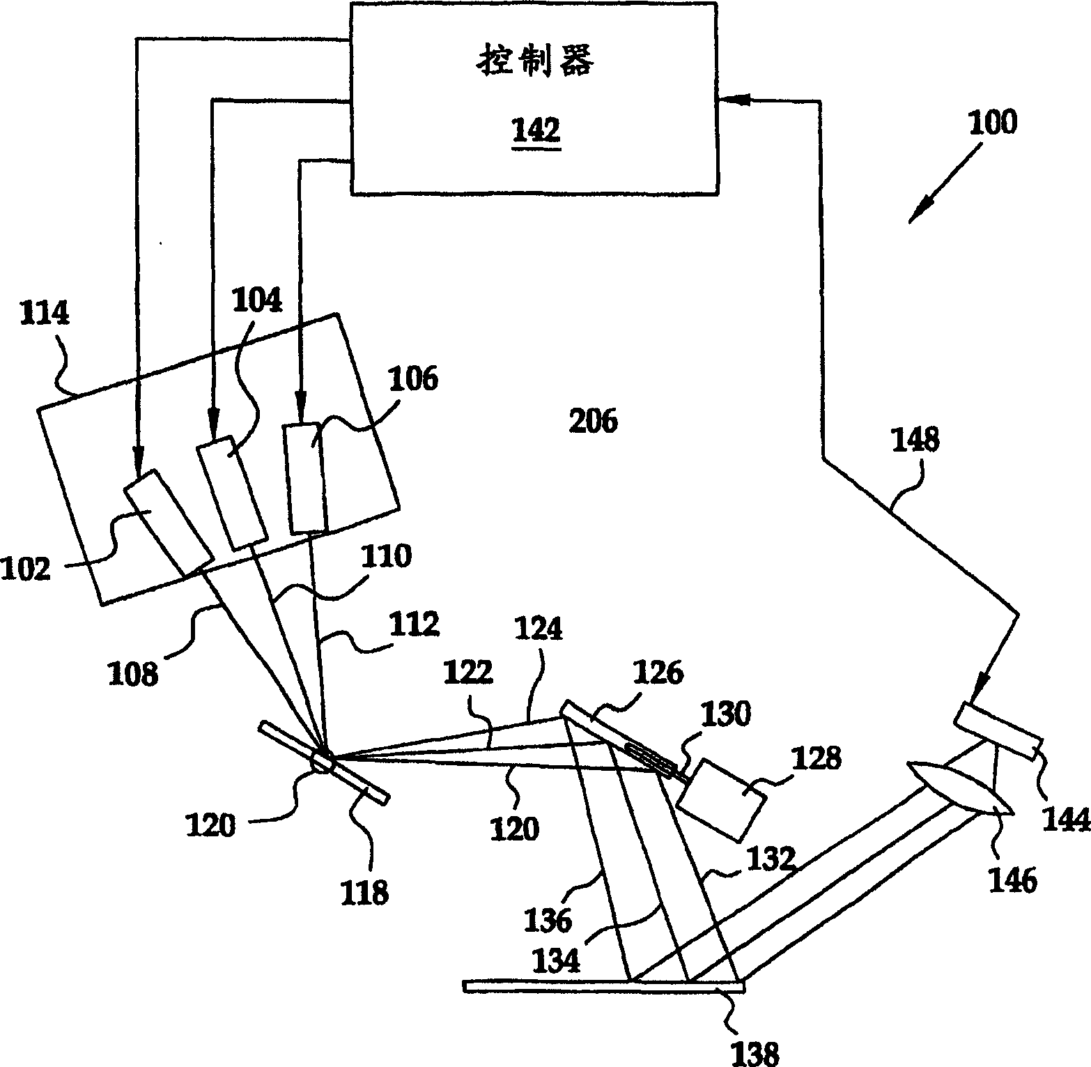
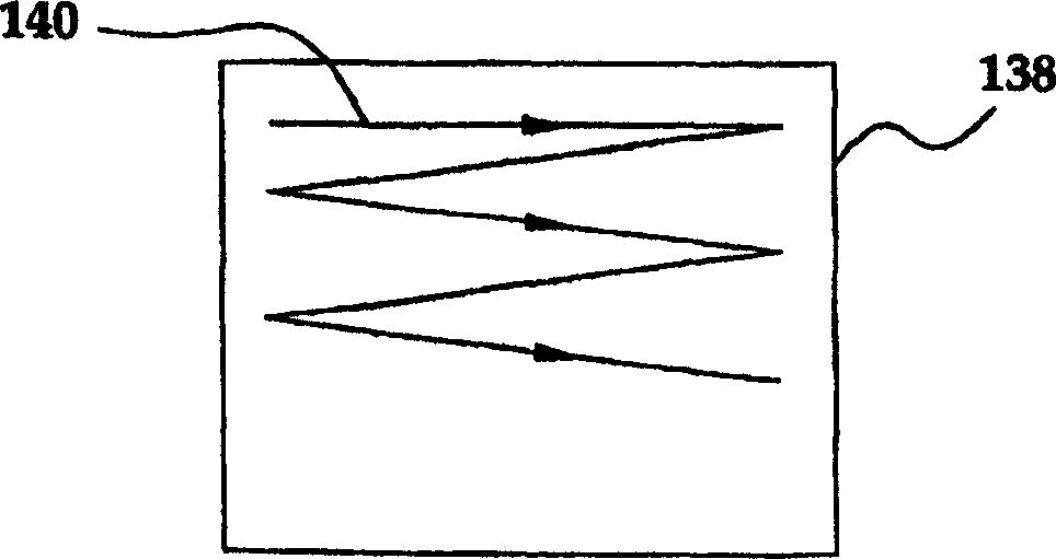
A method and apparatus are provided to controllably compensate for distortions in an image produced by an LPD, where the distortion arises from the shape and / or angle of the viewing surface relative to the LPD. For example, the LPD can determine the angle of the viewing surface relative to the LPD and then adjust the horizontal and vertical scan mechanisms to return the image to its original configuration, such as rectangular.

Description

technical field [0001] The present invention relates generally to electronic displays and, more particularly, to laser projection displays used to compensate for distortion in laser projection displays. Background technique [0002] In the field of image projection, any of a wide variety of distortions may appear on the projected image due, at least in part, to the shape and angle of the viewing surface relative to the angle at which the image is projected. For example, if the projector is placed at an angle relative to the viewing screen, the image has a trapezoidal shape that differs from its traditional rectangular configuration. Likewise, rectangular images projected onto curved surfaces will be distorted. So, the problem is complex and none of the proposed solutions have been successful in restoring the image to its desired rectangular structure without losing image resolution and without cumbersome and complex optics. [0003] It is an object of the present invention...

Claims


Application Information

Patent Timeline
Patent Type & Authority Applications(China)
IPC IPC(8): H04N9/31H04N5/74G03B21/00
Inventor 米克罗斯·斯坦恩保罗·德沃基斯纳拉彦·纳姆部迪利卡尔·维坦博格晨·谭雷·戈尔德曼迪米特利·亚维德福莱得里克·F.·伍德约瑟夫·凯兹
Owner SYMBOL TECH INC
Why Eureka
Try Eureka