
Stitch structure

A stitch and coil technology, applied in the field of stitch structure of double-thread lock stitching

Inactive Publication Date: 2007-03-21
YAMATO SEWING MASCH MFG CO LTD
View PDF0 Cites 10 Cited by
  • Summary
  • Abstract
  • Description
  • Claims
  • Application Information

AI Technical Summary

Problems solved by technology

The above-mentioned slack in the final stitch 2a / 2a is likely to occur when sewing with a soft upper thread 2 / 2 and a weak tension

Method used


Image

  • Stitch structure
  • Stitch structure
  • Stitch structure

Examples


Embodiment Construction

[0028] Hereinafter, the present invention will be described in detail based on the drawings showing preferred embodiments thereof.

[0029] Fig. 4 is a plan view showing the first embodiment of the stitch structure of the present invention, and Fig. 5 is a plan view showing the second embodiment of the stitch structure of the present invention, showing enlarged lines appearing near the terminal end of the backside of the fabric trace.

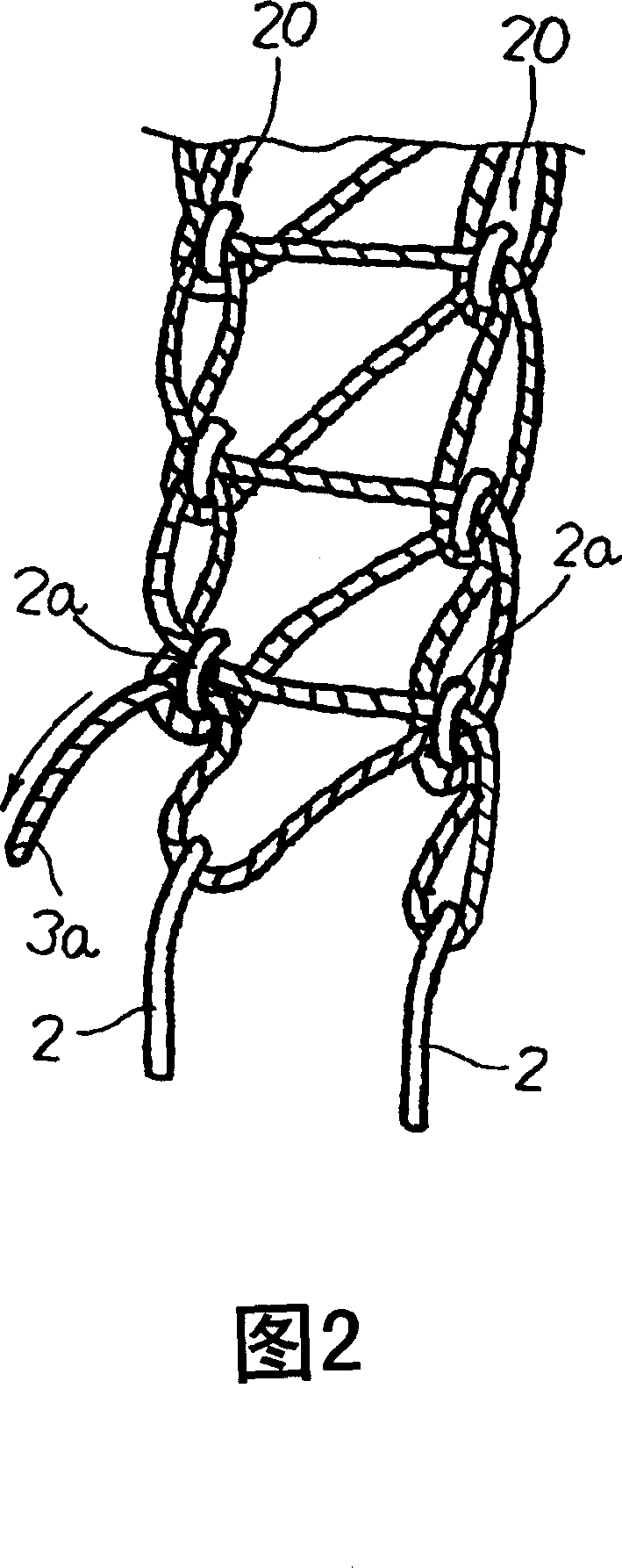
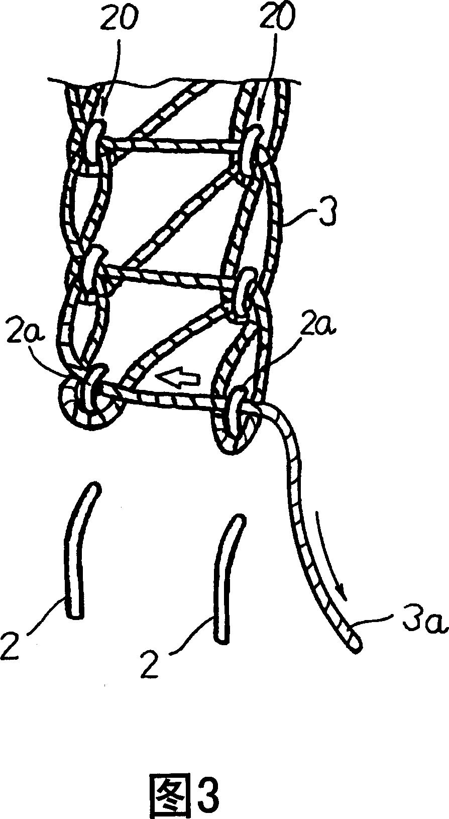
[0030] The stitch structure shown in Fig. 4 and Fig. 5 is the same as the stitch structure shown in Fig. 2 above, in that the loop thread 3 is entangled in the form of loop and (warp and weft) interweaving and formed by two surface threads 2 / 2. The stitch structure of the double-needle double-thread lockstitch on each stitch of the two stitch rows 20 / 20 arranged in parallel to each other.

[0031] The loop thread 3 is extracted from the coil (not shown) to the right side in Fig. 4 and Fig. 5 and goes out to the left side, and is interwoven wit...


PUM


Abstract

A stitch structure capable of effectively preventing the occurrence of raveling peculiar to double chain stitches irrespective of sewing conditions is provided by the stitch structure of double chain stitches including a plural number of needle threads forming rows of thread loops at the rear face of a cloth and one looper thread entwined with the rows of thread loops at the rear face of the cloth; wherein the looper thread is cut at one side of the positions at which it is entwined in the mode of interlacing with the preceding loops preceding to the final loops at the respective sewing termination ends of the respective rows of thread loops.

Description

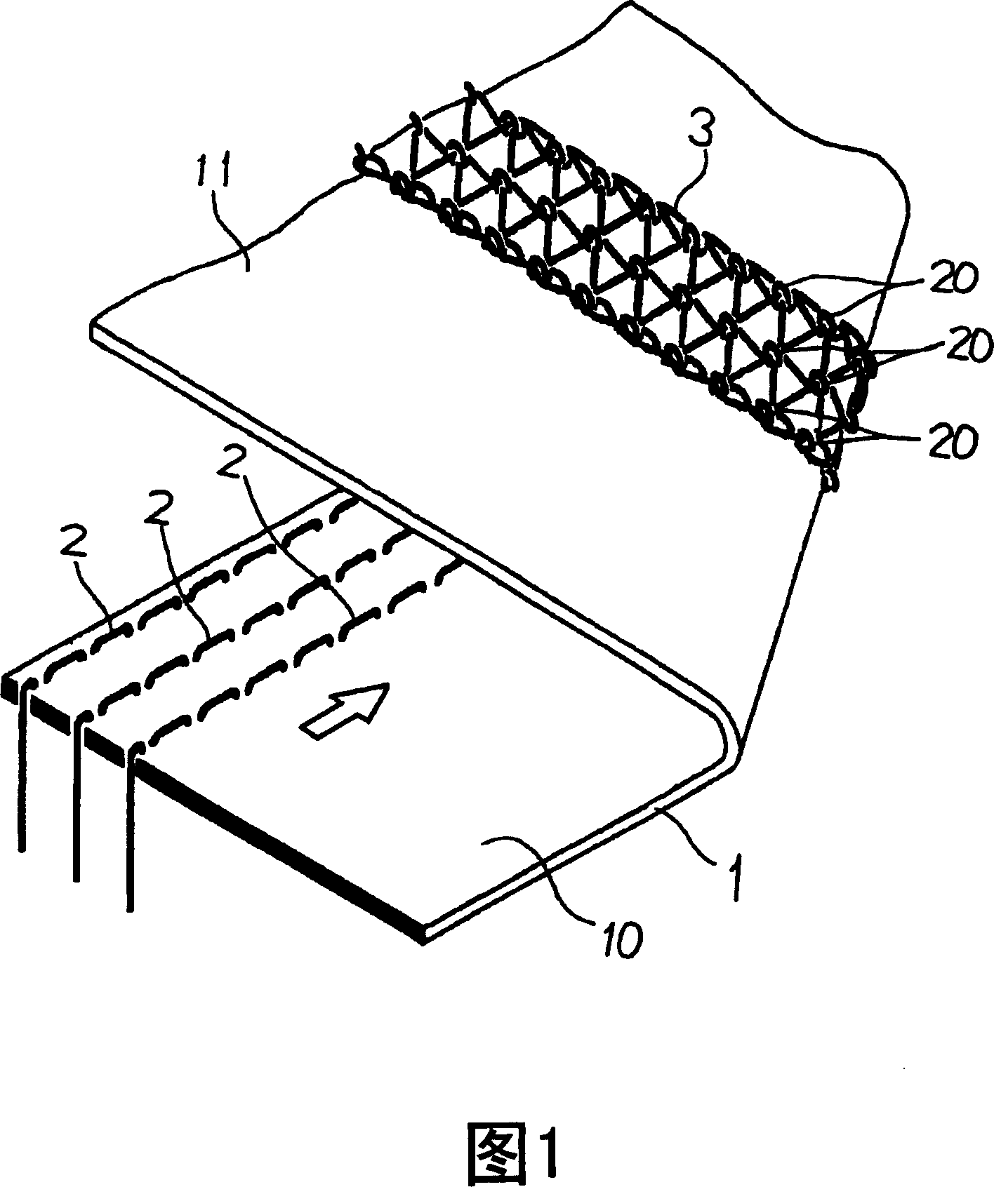
technical field [0001] The present invention relates to a stitch structure of Double Chain Stitches formed on a sewn product by a sewing machine, and more particularly to a stitch structure for preventing Snag Stitch at the end of sewing. Background technique [0002] In the process of sewing with a sewing machine, especially with an industrial sewing machine, various forms of stitch structures are used in order to suit the type and location of the sewing product. As one of such stitch structures, there is a double-thread overlock stitch structure represented by the symbol D in the Japanese Industrial Standard, and there is also a double-thread overlock stitch that is represented by the symbol F in the Japanese Industrial Standard. The stitch structure of the flat chain stitch in which decorative stitches are added to the upper decorative thread. [0003] Fig. 1 is an explanatory view of the stitch structure of the double overlock, showing the stitches of the overlock that ...

Claims


Application Information

Patent Timeline
Patent Type & Authority Applications(China)
IPC IPC(8): D05B1/08
CPCD05B1/08D05B1/10D05B93/00
Inventor 保泽纪
Owner YAMATO SEWING MASCH MFG CO LTD
Learn More