Electronic yarn trapper and sewing machine

A thread clamp and electronic technology, which is applied in the field of sewing machines, can solve the problems of premature loosening of the electronic thread clamp, unstable and uncontrollable working delay angle of the electronic thread clamp, and improve sewing quality and sewing efficiency. , avoid premature loosening of thread clamping, and improve the effect of stability

Active Publication Date: 2020-09-11
JACK SEWING MASCH CO LTD
View PDF7 Cites 3 Cited by
  • Summary
  • Abstract
  • Description
  • Claims
  • Application Information

AI Technical Summary

Problems solved by technology

During actual sewing, the thickness of the upper thread and the sewing speed of the first stitch of the sewing machine are constantly changing, which causes the working delay angle of the electronic thread tensioner to be very unstable and uncontrollable, resulting in premature or premature loosening of the thread by the electronic thread tensioner. Night
When the electronic thread clamp loosens the thread too early, the upper thread ends cannot be brought to the back of the sewing material, which affects the appearance of the sewing material; when the electronic thread clamp loosens the thread too late, it is easy to cause the thread to come off , the end of the upper thread comes out of the needle hole of the needle

Method used


Image

  • Electronic yarn trapper and sewing machine
  • Electronic yarn trapper and sewing machine
  • Electronic yarn trapper and sewing machine

Examples


Embodiment 1

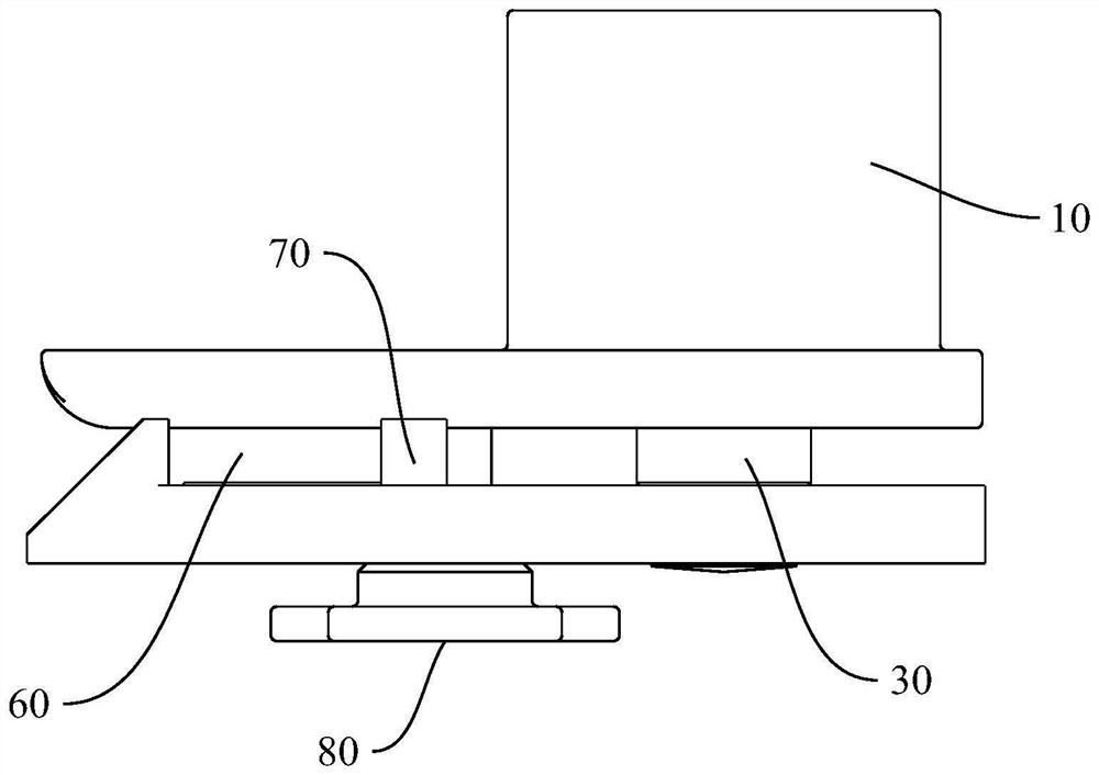
[0073] Embodiment one, as image 3 and Figure 4 As shown, the adjusting screw 70 includes a first threaded portion 71, a guide portion 72, and a second threaded portion 73 that are sequentially connected along its axial direction from front to back. The front clamping portion 11 of the electromagnet housing 10 is provided with a The threaded portion 71 is threaded into the threaded hole 12 , and the rear clamping portion 51 of the clamping cover 50 is provided with a guide hole 52 that guides and cooperates with the guide portion 72 . The second threaded portion 73 is threaded into the adjusting nut 80 . In this embodiment, the front end of the adjusting screw 70 is fixed in the front clamping portion 11 of the electromagnet housing 10 . Preferably, the outer diameter of the guide portion 72 is greater than the outer diameter of the second threaded portion 73 , and at the same time, the outer diameter of the guide portion 72 is also greater than the outer diameter of the fir...

Embodiment 2

[0074] Embodiment two, such as Figure 6 As shown, a first through hole 13 is opened in the front clamping part 11, a second through hole 53 is opened in the rear clamping part 51, and the adjusting screw 70 is penetrated in the first through hole 13, and the two guide and cooperate to adjust The screw 70 is passed through the second through hole 53 , and the two guide and cooperate. In this embodiment, the adjusting screw 70 is only passed through the front clamping portion 11 of the electromagnet casing 10 and the rear clamping portion 51 of the wire clamping cover 50 .


PUM


Abstract

The invention provides an electronic yarn trapper. The electronic yarn trapper comprises an electromagnet housing, an electromagnet coil, an iron core, a return spring, a yarn trapping cover plate, anadjusting bolt and an adjusting nut, wherein the electromagnet coil is mounted in the electromagnet housing; the iron core is matched with the electromagnet coil; the yarn trapping cover plate is fixed to the iron core; the adjusting bolt is parallel to the iron core; and the adjusting nut is connected with the adjusting bolt through threads; the two ends of the return spring abut against the electromagnet housing and the iron core, respectively; a yarn through groove allowing an upper thread to penetrate through is formed between the electromagnet housing and the yarn trapping cover plate; and the adjusting nut is arranged on one side, far away from the yarn through groove, of the yarn trapping cover plate and abuts against the yarn trapping cover plate. According to the electronic yarntrapper, the size of the yarn through groove is adjustable; when the thickness of the upper thread and the sewing speed of a first stitching of the sewing machine are changed, the working delay angleof the yarn trapper can be adjusted by adjusting the size of the yarn through groove so that the working delay angle of the yarn trapper is always kept within a range; and therefore, the working delayangle of the yarn trapper is controllable, and the stability of the working delay angle of the electronic yarn trapper is improved.

Description

technical field [0001] The invention relates to an electronic wire clamp. [0002] The present invention also relates to a sewing machine equipped with the above-mentioned electronic thread tensioner. Background technique [0003] At present, electronic thread clamps are usually installed in sewing machines to eliminate the "bird's nest" phenomenon and improve sewing quality; for example, a sewing machine thread clamping mechanism disclosed in the Chinese Utility Model Patent Application No. It is an electronic thread tensioner; another example is an electronic thread tensioner for sewing machines disclosed in Chinese Utility Model Patent No. 201420557309.6. After the last sewing is completed and the thread is trimmed, and when the first stitch is started next time, the electronic thread clamp works to clamp the section of upper thread between the needle side and the thread supply cylinder. The needle carries the upper thread and stabs the material downwards. The hook hook...

Claims


Application Information

Patent Timeline
Patent Type & Authority Applications(China)
IPC IPC(8): D05B47/04
CPCD05B47/04
Inventor 吴善敏林晓晓洪志敏
Owner JACK SEWING MASCH CO LTD
Why Eureka
Try Eureka