Planar invented F multi-frequency antenna

A multi-frequency antenna, plane technology, applied in the direction of the antenna, electrical components, radiating element structure, etc., can solve the problem of increasing the height of the antenna

Inactive Publication Date: 2010-07-28
SHANGHAI JIAO TONG UNIV
View PDF4 Cites 0 Cited by
  • Summary
  • Abstract
  • Description
  • Claims
  • Application Information

AI Technical Summary

Problems solved by technology

but increased the height of the antenna

Method used


Image

  • Planar invented F multi-frequency antenna
  • Planar invented F multi-frequency antenna

Examples


Embodiment Construction

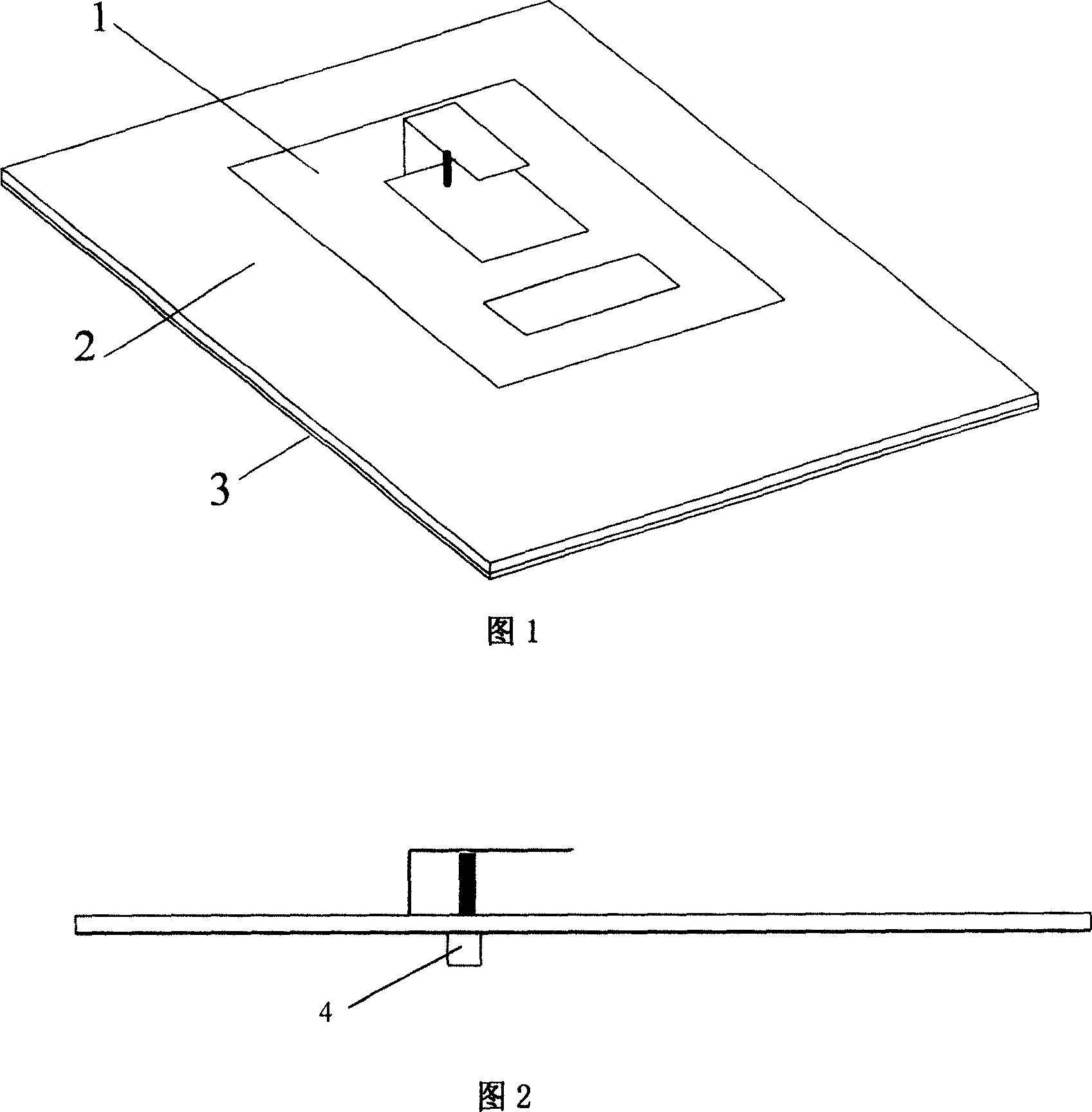
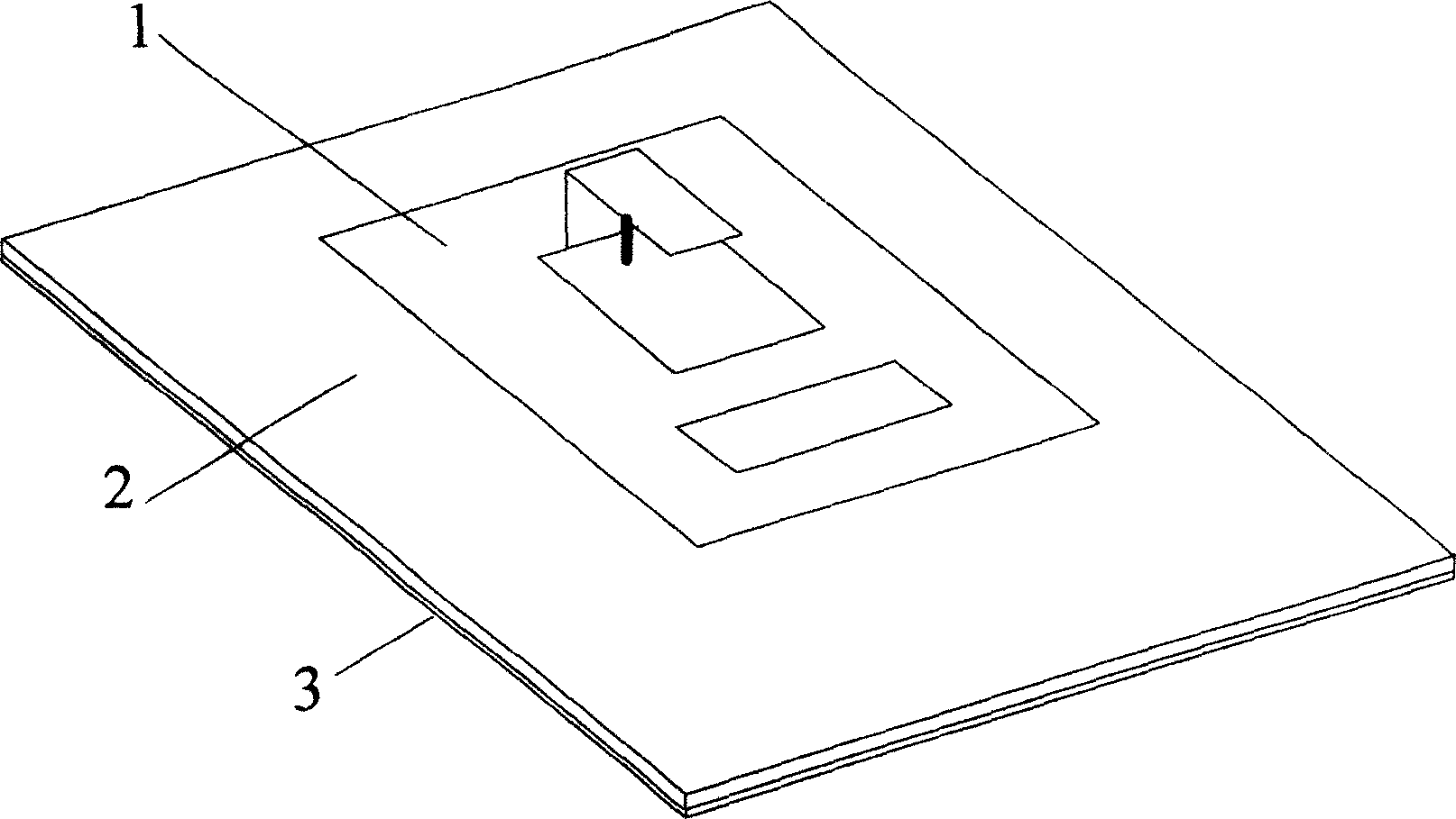
[0013] Such as figure 1 , figure 2 As shown, this embodiment includes: a radiation unit 1 , a dielectric plate 2 , a ground plate 3 and a feed port 4 . The radiating unit 1 , the dielectric plate 2 and the ground plate 3 are closely arranged sequentially from top to bottom.

[0014] The radiation unit 1 is composed of a rectangular metal thin substrate and a thin plate with a 90° bend connected to it. There are two rectangular windows in the center of the rectangular metal thin substrate, and one side of the thin plate with a 90° bend is connected to One of the rectangular windows is connected to the edge near the edge of the thin metal substrate and is perpendicular to the thin rectangular metal substrate, and the other side of the thin plate with a 90° bend is parallel to the thin rectangular metal substrate.

[0015] A rectangular dielectric plate 2 is adjacent to the rectangular metal thin substrate of the radiation unit 1 , and a metal grounding plate 3 is adjacent to ...


PUM


Abstract

A plane inverse F multi-frequency antenna including: a radiation unit, a medium plate, an earth plate and a feed port arrayed downward from the top, in which, said feeding port is placed under the metal earth plate and closing to it, said radiation unit is composed of a rectangle metal thin base plate and a thin plate with 90 deg. angle and connected to it, the center of the base plate is opened with two rectangle windows, one side of the plate with 90deg. angle is connected with the edge of the rectangular window closing to the edge of the base plate and vertical to the metal thin base plate, the other side of the plate with 90deg. angle is parallel to the thin base plate.

Description

technical field [0001] The invention relates to an antenna used in the technical field of communication, in particular to a planar inverted-F multi-frequency antenna. Background technique [0002] In the prior art, a single-whip antenna or a helical antenna is generally used in a communication terminal, and the size is relatively large. The later improved inverted-F antenna, although reduced in size, was only used for single-frequency work. [0003] After searching the literature of the prior art, it was found that in 2004, RongLin Li et al. published an article " "Development and Analysis of a Folded Shorted-Patch Antenna with ReducedSize" (Development and Analysis of a Folded Shorted-Patch Antenna with ReducedSize), proposed an improved planar inverted-F antenna, through the top and open side of the planar inverted-F antenna Load an inverted L-shaped patch to achieve dual-frequency operation. But the height of the antenna is increased. Contents of the invention [00...

Claims


Application Information

Patent Timeline
Patent Type & Authority Patents(China)
IPC IPC(8): H01Q13/08H01Q1/36H01Q1/38
Inventor 耿军平金荣洪韩福郭宪广丁敏
Owner SHANGHAI JIAO TONG UNIV
Why Eureka
Try Eureka