Bicycle shift operating device

An operating device, bicycle technology, applied in the direction of bicycle gear shifting mechanism, bicycle accessories, transportation and packaging, etc., can solve the problem of not being able to respond to the preferences of cyclists

Active Publication Date: 2007-04-11
SHIMANO INC
View PDF0 Cites 6 Cited by
  • Summary
  • Abstract
  • Description
  • Claims
  • Application Information

AI Technical Summary

Problems solved by technology

However, in the above-mentioned prior art, the operation direction of the input membe...

Method used


Image

  • Bicycle shift operating device
  • Bicycle shift operating device
  • Bicycle shift operating device

Examples


no. 1 Embodiment approach

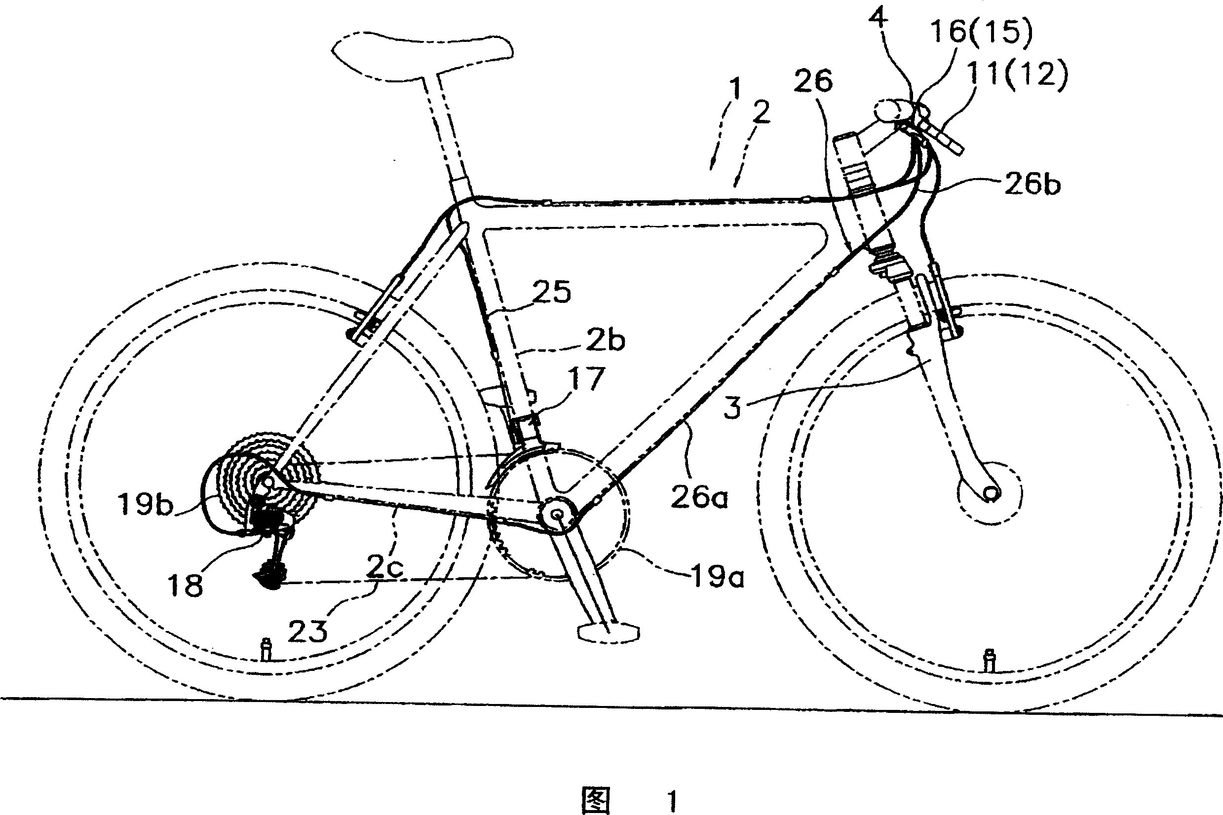
[0042] In FIG. 1 , a bicycle 1 on which the first embodiment of the present invention is mounted includes a frame 2 having a front suspension fork 3 and a handle bar 4 fixed to an upper portion of the front suspension fork 3 . A front derailleur 17 constituting an external transmission is attached to the middle portion of the body frame 2 , and a rear derailleur 18 is attached to the rear end portion of the body frame 2 . The front derailleur 17 is arranged, for example, at the lower portion of the seat tube 2b of the body frame 2, and guides the chain 23 to, for example, any one of the three front sprockets 19a. The rear derailleur 18 is arranged on the rear end portion of the chain stay 2c of the body frame 2, and guides the chain 23 to, for example, any sprocket of the rear sprocket 19b having eight sprockets. The front derailleur 17 and the rear derailleur 18 are connected to a front shift operating unit 15 and a rear shift operating unit 16 (an example of a shift operatin...

no. 2 Embodiment approach

[0071] In the above-mentioned first embodiment, the first operating member for performing the cable release operation is constituted by the operating member and the input member, but the second operating member 138 may be constituted by the operating member 168 and the input member 170 as shown in FIG. 8 . In addition, in FIG. 8 , the first operating member 36 is also composed of the operating member 68 and the input member 70 in the same manner as the above-mentioned embodiment, but the first operating member 36 may be integrally formed and the cable release may be performed by operating in one direction. operate. In the following description, the same symbols are attached to the same components as those of the first embodiment, and the components corresponding to the first embodiment are described by changing the symbols of the hundreds place.

[0072] In addition, in the second embodiment, except for the second operation member 138 and the cover 144 , other configurations a...

no. 3 Embodiment approach

[0082] In the first and second embodiments described above, the second coil spring 86 is provided, but the second coil spring 86 may not be provided. In addition, the positions of the first restricting part 68a and the second restricting part 70d as the first contact part are not limited to the above two embodiments. In the third embodiment, the configuration other than the first operating member is the same as that of the first embodiment, so description thereof will be omitted.

[0083] In the third embodiment, as shown in FIG. 9 , the second coil spring is not provided. Therefore, the spring hook part etc. which are attached to the 2nd coil spring are not provided either. In addition, the positions of the first restricting portion 268a and the second restricting portion 270d are different. In addition, since the details of the structure and operation of the rear shift operation unit 216 other than the first operation member 236 are the same as those of the first embodimen...


PUM


Abstract

The present invention is to make it possible to adapt an operating direction of an input member to a rider's preference, in a bicycle shift operating device having the input member. A rear shift operating part 16 includes a mounting part 30 mountable to a bicycle, a winding body 32, a position holding and releasing mechanism 34, an action member 68, and an input member 70. The winding body is mounted to the mounting part movably in a cable pulling direction and a cable releasing direction. The position holding and releasing mechanism selectively holds the cable catching body in any one of a plurality of holding positions corresponding to a plurality of shift positions. The action member is mounted to the mounting part swingably around a first shaft, and causes the position holding and releasing mechanism to act by swing to a shift position from a neutral position to move the winding body in the cable pulling direction. The input member is mounted to the action member and moves the action member to the shift position from the neutral position by movement to a first direction and a second direction.

Description

technical field [0001] The present invention relates to an operating device, in particular to a bicycle shifting operating device mounted on a bicycle. Background technique [0002] Some bicycles are equipped with a transmission such as a built-in transmission or an external transmission. In order to perform the shifting operation of these shifting devices, a shifting operation device connected to the shifting device via a shifting cable is used. As a conventional shift operation device, a lever type shift device having a winding lever (an example of an input member) and a release lever (an example of an input member) is known. In lever-type transmissions, there are known techniques for swinging a winding lever and a release lever in the same direction (for example, refer to Patent Document 1) and techniques for swinging and operating them in different directions (for example, see Patent Document 2). In the former conventional technique, when the winding lever and the rele...

Claims


Application Information

Patent Timeline
IPC IPC(8): B62M25/04
Inventor 川上龙也
Owner SHIMANO INC
Why Eureka
Try Eureka