Ultralong orientational carbon nano-tube filament/film and its preparation method

A technology of carbon nanotube film and carbon nanotube, which is applied in the direction of oriented carbon nanotube, carbon nanotube, nanostructure manufacturing, etc.

Active Publication Date: 2007-04-18
TSINGHUA UNIV
View PDF4 Cites 84 Cited by
  • Summary
  • Abstract
  • Description
  • Claims
  • Application Information

AI Technical Summary

Benefits of technology

Inventions have several technical benefits that make it easier than previous methods for producing large quantities of carbon nano tubules (CNTs) without requiring expensive equipment like platinum electrodes. These new techniques allow CNTs to grow at higher temperatures while still being able to move around within them. Additionally, they are more flexible when compared to traditional methods where there needs an external support material such as glass wool or paper.

Problems solved by technology

Technological Problems This patented technology describes methods used to make small amounts of carbon nanoparticles called nanosphericles or quantum dots. These particles are tiny objects made up from atoms arranged into regular patterns like crystalline solids. They have many potential uses including use in electronic devices and biomedical applications due their unique properties.

Method used


Image

  • Ultralong orientational carbon nano-tube filament/film and its preparation method
  • Ultralong orientational carbon nano-tube filament/film and its preparation method
  • Ultralong orientational carbon nano-tube filament/film and its preparation method

Examples


Embodiment 1

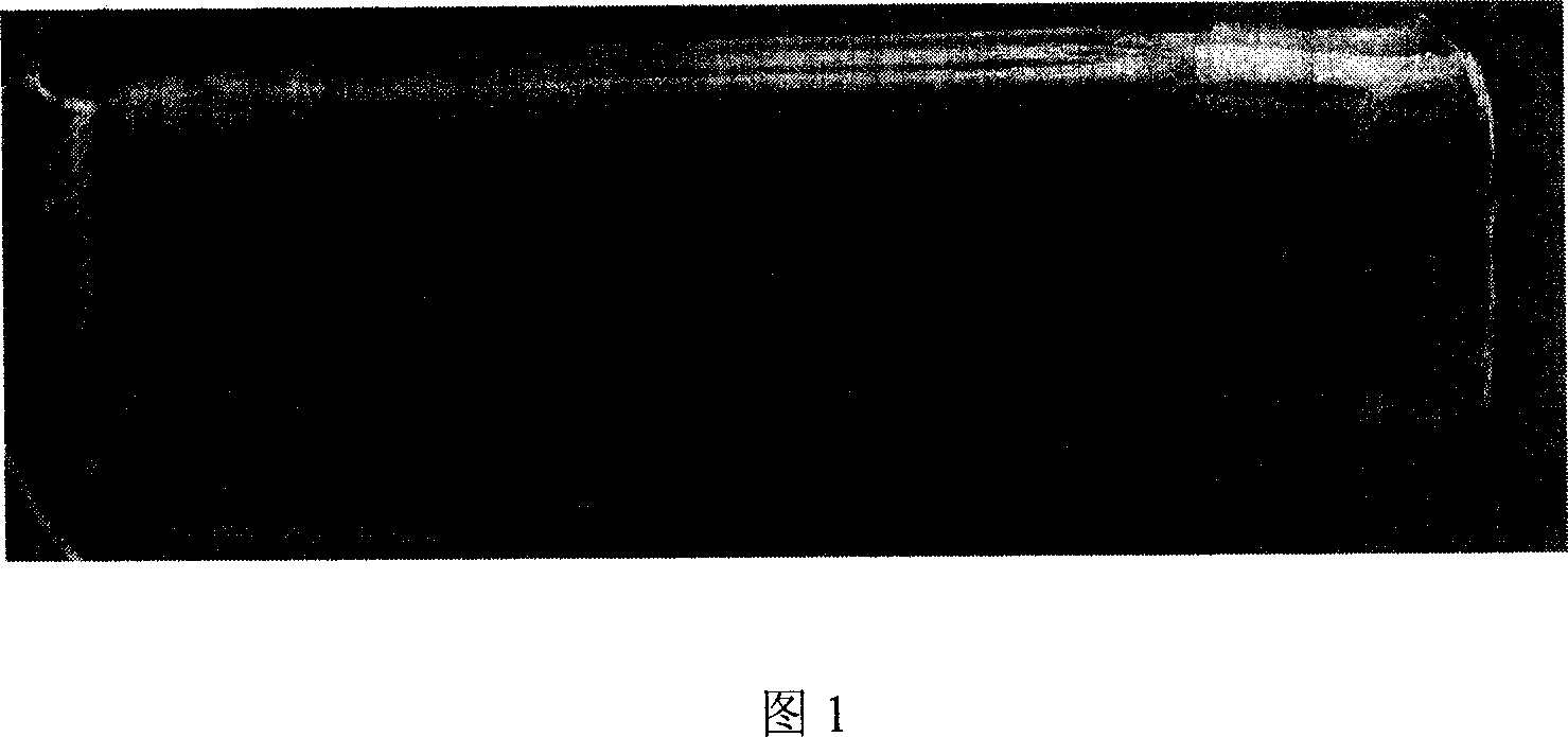
[0029] Embodiment 1. This embodiment investigates the preparation of carbon nanotube arrays by the flotation method, adopting a silicon dioxide sheet with an infinite radius of curvature of 1 mm in thickness and 25 mm in length and width of 25 mm as a substrate, and then putting the ball particles into a fixed bed for reaction In the reactor, the temperature was raised to the reaction temperature of 900° C. under the atmosphere of hydrogen and argon. Then, a cyclohexane solution of ferrocene is introduced, the carbon nanotube catalyst precursor ferrocene decomposes in situ to form an iron catalyst, and the carbon source is catalyzed and cracked to form a carbon nanotube array. After 2.5 hours, an array with a length of 5.4 mm can be obtained on the surface of the silicon dioxide wafer (Fig. 1).

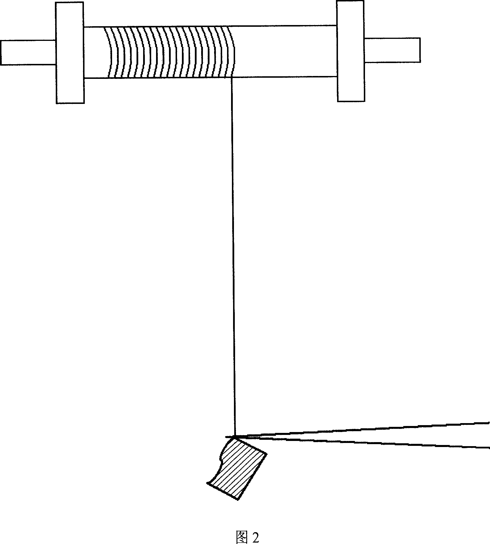
[0030] Take out the silicon dioxide substrate, keep the array on its surface, and directly use the stretching tool tweezers to pull a selected section of the carbon nanotube array inc...

Embodiment 2

[0033] Example 2. A silica / zirconia composite ball with a radius of curvature of 1 mm was used as a substrate, and the ball was placed in a moving bed reactor, and the temperature was raised to a reaction temperature of 750° C. under an atmosphere of hydrogen and nitrogen. Then a xylene solution containing 1:1 nickelocene and ferrocene is introduced, the catalyst precursor is decomposed in situ to form a carbon nanotube catalyst, and the carbon source is catalytically cracked to form a carbon nanotube array. An array with a length of 0.5 mm can be obtained on the surface of the ball after 1 hr.

[0034] Peel off the carbon nanotube array obtained above from the surface of the silica sphere, and then use a fixed stretching die to draw a selected section of the carbon nanotube array including one end of a plurality of carbon nanotube bundles to extract a carbon nanotube with a diameter of about 100 μm. The nanotube bundle is continuously stretched at a speed of 0.01m / s, and afte...

Embodiment 3

[0035]Example 3. Quartz fibers with a radius of curvature of 10 μm were used as substrates, and then the fibers were placed in a moving bed reactor, and the temperature was raised to a reaction temperature of 800° C. under an atmosphere of hydrogen and argon. Then a benzene solution of cobalt carbonyl is passed through, the cobalt carbonyl is decomposed in situ to form a nickel catalyst, and the carbon source is catalytically cracked to form a carbon nanotube array. After 0.8hr, an array with a length of 0.3mm can be obtained on the surface of the quartz fiber.

[0036] Take out the quartz fiber covered with the array, keep the array on its surface, directly use the stretching tool tweezers to pull a selected section of the carbon nanotube array including one end of a plurality of carbon nanotube bundles to extract the carbon nanotube bundle with a diameter of 0.8 μm, and pass through Stretching at a speed of 0.1 cm / s is continued, and after 10 minutes of stretching, the carbo...


PUM

PropertyMeasurementUnit
Lengthaaaaaaaaaa
Diameteraaaaaaaaaa
Thicknessaaaaaaaaaa

Abstract

The present invention relates to an ultralong oriented carbon nano tube wire/film and its preparation method. The described carbon nano tube wire/film is made up by using mutually-winded and connected tube bundle end portions of several bundles of carbon nano tubes, their orientations are basically identical, the macrodiameter is above micrometer grade, length is above centrimeter grade, the macrothickness of carbon nano tube film is above several tens nanometers, its width is above several tens micrometers and its length is above centrimeter grade. Its preparation method includes the following steps: utilizing floatation process to make the carbon nano tube array be grown out from base surface, then using tension tool to draw carbon nano tube wire or film from one end of carbon nano tube array, utilizing continuous tension to make the tube bundle of carbon nano tube be formed into oriented carbon nano tube wire/film along the tension direction.

Description


Claims


Application Information

Patent Timeline
Owner TSINGHUA UNIV
Why Eureka
Try Eureka