Plasma display apparatus and driving method therof

A display device, plasma technology, used in static indicators, identification devices, instruments, etc., can solve problems such as data driver IC damage

Inactive Publication Date: 2007-04-18
LG ELECTRONICS INC
View PDF0 Cites 2 Cited by
  • Summary
  • Abstract
  • Description
  • Claims
  • Application Information

AI Technical Summary

Problems solved by technology

[0007] Specifically, when the image data is a specific pattern in which logic values ​​1 and 0 are repeatedly input, the displacement current flowing in the data driver IC increases excessively, so that The data driver IC is electrically damaged

Method used


Image

  • Plasma display apparatus and driving method therof
  • Plasma display apparatus and driving method therof
  • Plasma display apparatus and driving method therof

Examples


Embodiment Construction

[0027] Preferred embodiments of the present invention will be described in more detail with reference to the accompanying drawings.

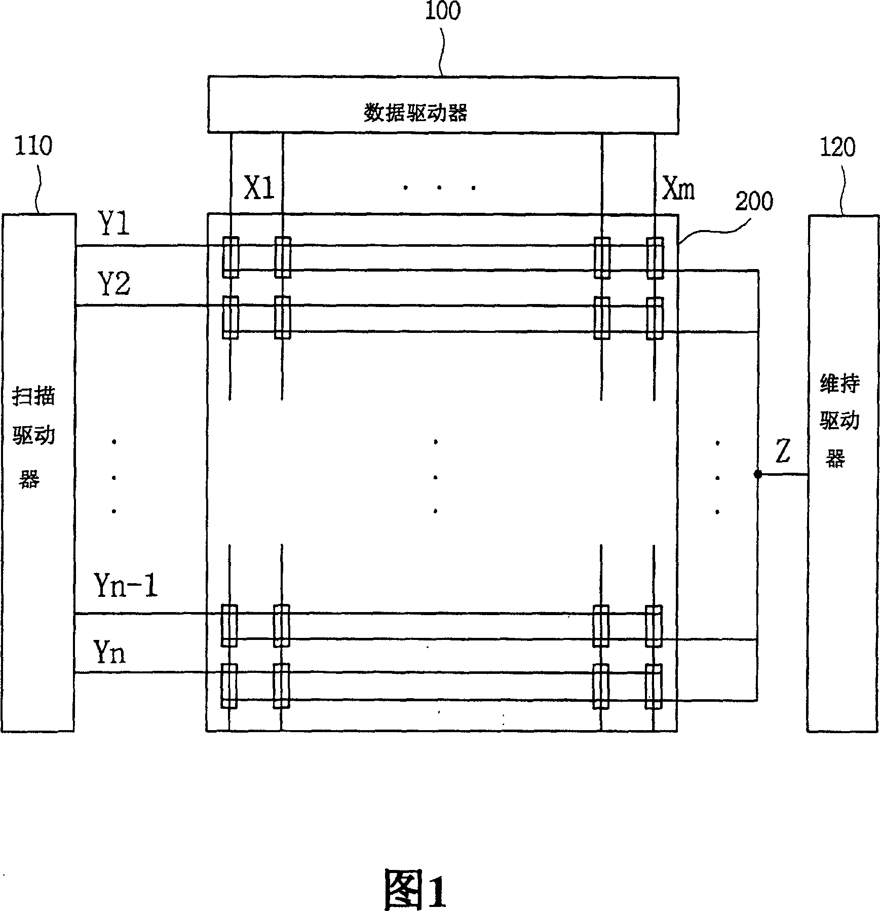
[0028] A plasma display device, comprising: a plurality of scan electrodes, a plurality of data electrodes provided with data signals; a scan driver for providing scan signals to the plurality of scan electrodes using a first scan type in a first subfield of a frame , and for supplying scan signals to a plurality of scan electrodes using a second scan type in a second subfield of a frame, the second scan type directing the scan driver to provide scan signals in an order different from that of the first scan type; and a data driver , for supplying data signals corresponding to scan signals supplied in the first subfield and the second subfield to the plurality of data electrodes, wherein the scan driver continuously supplies the first scan signal and the second scan signal to the plurality of scan electrodes The first scan electrode and the secon...


PUM


Abstract

A plasma display apparatus and a method of driving the same are disclosed. In the plasma display apparatus, a scan driver supplies scan signals to a plurality of scan electrodes using a first scan type in a first subfield of a frame, and supplies the scan signals to the plurality of scan electrodes using a second scan type, which directs the scan driver to supply the scan signals in an order different from the first scan type, in a second subfield of the frame. Further, the scan driver consecutively supplies a first scan signal and a second scan signal to a first scan electrode and a second scan electrode of the plurality of scan electrodes. A supply end time point of the first scan signal is later than a supply start time point of the second scan signal.

Description

technical field [0001] The present invention relates to a plasma display device and a driving method thereof. Background technique [0002] A plasma display panel includes a front panel, a rear panel, and barrier bars formed between the front panel and the rear panel. The barrier ribs form a unit discharge cell or a plurality of discharge cells. Each discharge cell is filled with a main discharge gas including, for example, neon (Ne), helium (He), and a mixture of Ne and He, and an inert gas of a small amount of xenon (Xe). When discharged by a high-frequency voltage, the inert gas generates vacuum ultraviolet rays, thereby causing fluorescent materials formed in the discharge cells to emit light, thereby displaying images. Since the plasma display panel can be manufactured thin and light, it has drawn attention as a next generation display device. [0003] A plurality of electrodes such as scan electrodes, sustain electrodes and data electrodes are formed in the plasma d...

Claims


Application Information

Patent Timeline
Patent Type & Authority Applications(China)
IPC IPC(8): G09G3/28G09G3/20H01J17/49G09F9/313G09G3/288G09G3/293
CPCG09G2310/0213G09G3/2022G09G2330/025G09G2330/04G09G2310/0218G09G3/293G09G3/291G09G3/296
Inventor 朴记洛裵钟运柳圣焕赵允珠黃斗勇
Owner LG ELECTRONICS INC
Why Eureka
Try Eureka