

Rotating assembly
A technology of rotating components and internal rotation, which is applied to digital data processing components, telephone structures, instruments, etc., and can solve problems such as inconvenient use
- Summary
- Abstract
- Description
- Claims
- Application Information
AI Technical Summary
Problems solved by technology
Method used
Image

Examples
Embodiment Construction
[0015] A preferred embodiment of the rotary slide assembly of the present invention is described in detail as follows.
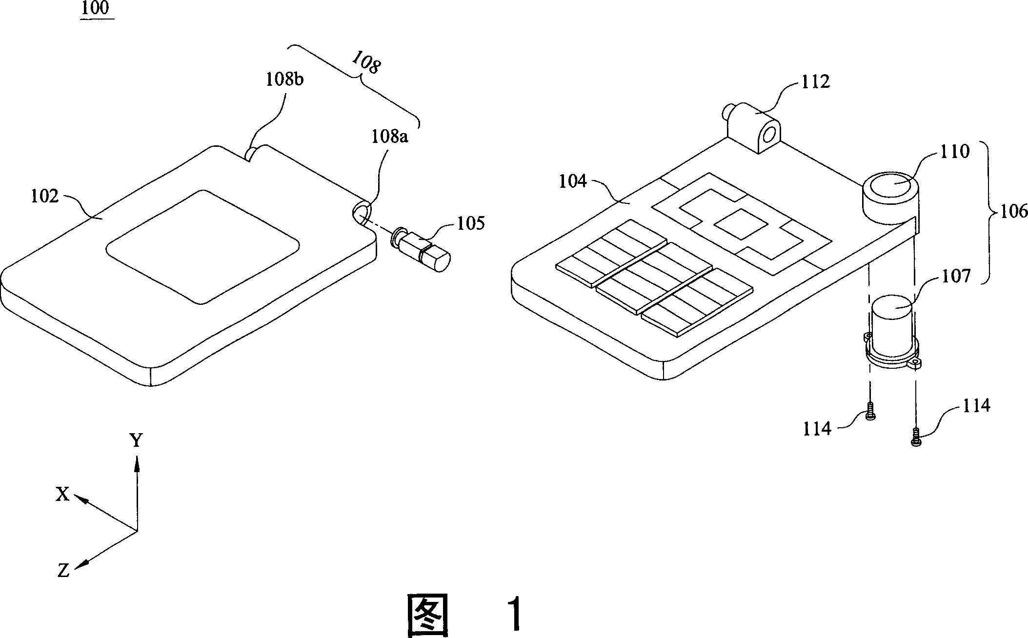
[0016] FIG. 1 is an exploded perspective view of a handheld mobile device with a rotating assembly according to an embodiment of the present invention. According to a preferred embodiment of the present invention, the rotating component is used in a flip-type handheld mobile device 100 . As shown in the figure, the handheld mobile device 100 includes a cover 102 , a base 104 and a rotating component 106 . And a display (not shown in the figure) is assembled in the upper cover 102 . The first end 108a of the first coupling portion 108 of the upper cover 102 is connected to the second coupling portion 110 on the base 104 through the rotating component 106 . The second end 108 b of the first coupling portion 108 is connected to the third coupling portion 112 on the base 104 . According to the present invention, the third coupling portion 112 on the base 104 ...
PUM
 Abstract
Description
Claims
Application Information