Cooling starting valve structure in fuel battery vehicle

A fuel cell, cold start technology, applied in fuel cells, fuel cell additives, fuel cell heat exchange, etc., can solve problems such as the need for thawing time and the consumption of thawing energy

Active Publication Date: 2007-06-27
HYUNDAI MOTOR CO LTD
View PDF0 Cites 5 Cited by
  • Summary
  • Abstract
  • Description
  • Claims
  • Application Information

AI Technical Summary

Problems solved by technology

[0007] However, the conventional cooling system for fuel cell vehicles has a problem in that the ice of each drain valve 7 is thawed using an additional heating device, thus requiring thawing time and consuming thawing energy

Method used


Image

  • Cooling starting valve structure in fuel battery vehicle

Examples


Embodiment Construction

[0017] Hereinafter, preferred embodiments of the present invention will be described with reference to the accompanying drawings.

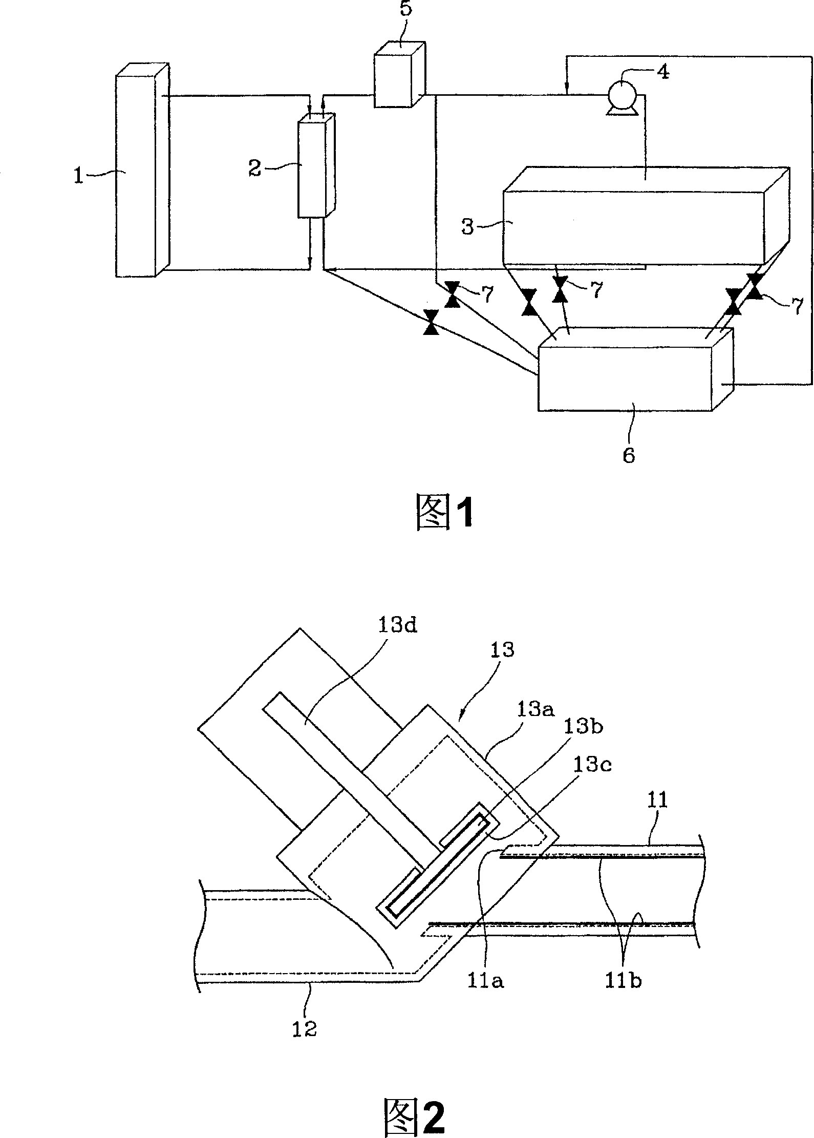
[0018] Fig. 2 shows a section of a cold start valve for a fuel cell vehicle according to the present invention. That is, the inlet pipe 11 and the outlet pipe 12 are arranged parallel to each other. The inlet pipe 11 is connected to a second cooling path of cooling water which circulates from the fuel cell stack through the heat exchanger and cools the fuel cell stack. The discharge pipe 12 is connected with the quick thawing device. The two pipes 11 and 12 are connected to communicate with each other through a valve body 13 a of a cold start valve 13 .

[0019] The two tubes are arranged parallel to each other. Therefore, in order to open or close the inlet pipe 11, the outlet of the inlet pipe 11 is cut to have an oval shape, thereby forming the oval valve seat 11a. The valve seat 11a is connected to and communicates with the valve body 13a....


PUM


Abstract

The present invention provides a cold start valve structure in a fuel cell vehicle, comprising: (a) an inlet pipe having an elliptical valve seat; (b) an outlet pipe arranged to be parallel to the inlet pipe; and (c) a valve body connecting to the inlet pipe and the outlet pipe such that the inlet pipe is in communication with the outlet pipe, the valve body being inclined with respect to the inlet pipe at a predetermined angle. An exalting vavle is provided in the valve body which has the same inclined angle with valve body and can move up and down for opening or closing the valve base.

Description

technical field [0001] The present invention relates to a cold start valve for a fuel cell vehicle, and more particularly, to a cold start valve for a fuel cell vehicle, which has a good discharge capability so that a driving operation can be performed without consuming extra energy, And it does not require a defrosting time, so that the fuel cell vehicle can be started instantly, and it can ensure stability even when the car is started at sub-zero temperature. Background technique [0002] As shown in FIG. 1 , a conventional cooling system for a fuel cell vehicle includes a first cooling path and a second cooling path. The first cooling path has cooling water circulating in the radiator 1 and the heat exchanger 2 . The second path has cooling water circulating from the fuel cell stack 3 to the heat exchanger 2 through the pump 4 and the water storage tank 5 . [0003] Therefore, a heat exchange operation between the cooling water in the fuel cell stack 3 and the cooling w...

Claims


Application Information

Patent Timeline
Patent Type & Authority Applications(China)
IPC IPC(8): B60L11/18H01M8/04
CPCY02E60/50H01M8/04253H01M8/04007Y10T137/7036H01M8/04
Inventor 李承镛金圣均
Owner HYUNDAI MOTOR CO LTD
Why Eureka
Try Eureka