Engine cold-start preheating device

A technology of preheating device and engine, which is applied in the direction of engine starting, engine components, combustion engine, etc., can solve the problem of uneven heat storage and heat release process, low sensible heat storage and heat storage density, limited engine preheating function, etc. problems, to enhance the defrosting effect and heating effect, fast warm-up, improve emissions and cold start performance.

Inactive Publication Date: 2013-04-24
NINGBO INST OF TECH ZHEJIANG UNIV ZHEJIANG
View PDF7 Cites 13 Cited by
  • Summary
  • Abstract
  • Description
  • Claims
  • Application Information

AI Technical Summary

Problems solved by technology

The most primitive method is that the driver directly heats the bottom of the engine with a gasoline blowtorch and other ignition methods, and then ignites and starts. This method has low efficiency, high labor intensity, slow temperature rise, and potential safety hazards; It will cause severe wear and tear of the engine block and reduce the life of the engine; domestic patent technical materials also introduce the use of electric heating to preheat the engine, which is obviously not energy-saving; some patents propose to use the heat storage of engine cooling water into the thermal insulation container, and then return the stored heat to the engine during cold start. Although these patents have different ways of realizing heat storage and heat release, the common deficiency is that they all use the sensible heat storage method of engine cooling water to carry out Heat storage, sensible heat storage has low heat storage density, large volume size, unstable heat storage and heat release process, and when engine cooling water is used for heat storage, the maximum heat storage temperature can only be controlled at 85°C-90°C, All of these have resulted in the small heat storage capacity of this heat storage method, the long heat storage time, and the limited warm-up function of the engine.

Method used


Image

  • Engine cold-start preheating device
  • Engine cold-start preheating device
  • Engine cold-start preheating device

Examples


Embodiment Construction

[0021] The present invention will be further described below in conjunction with accompanying drawing.

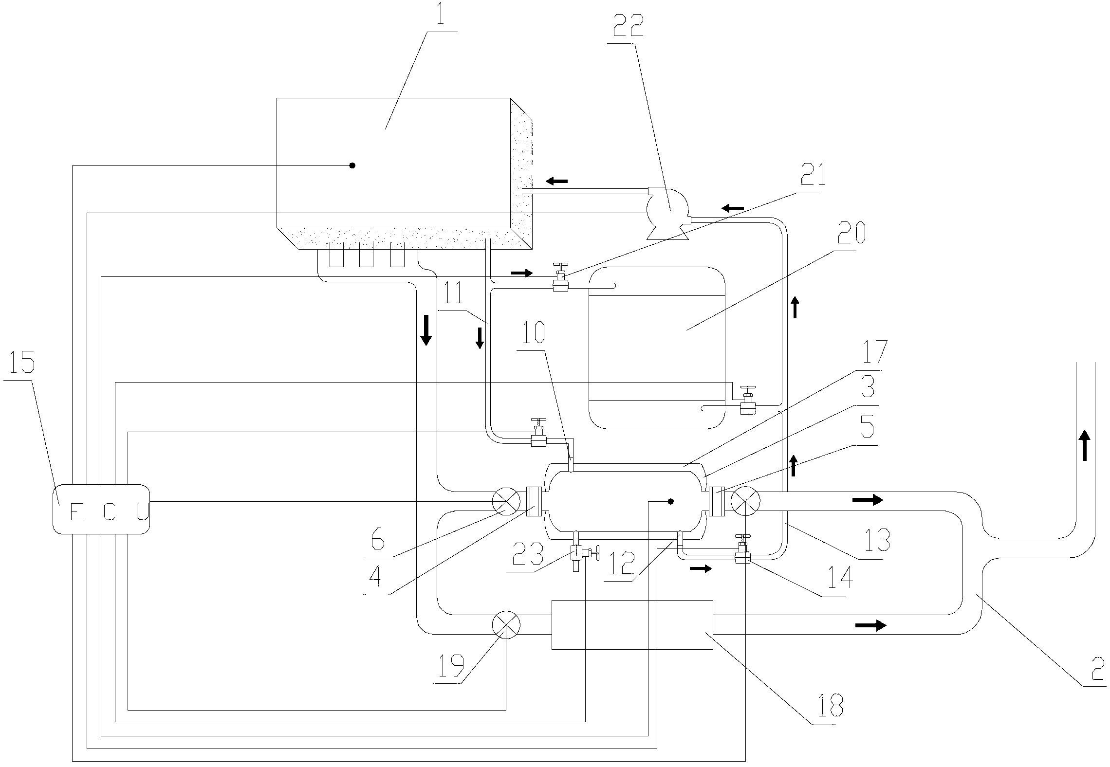
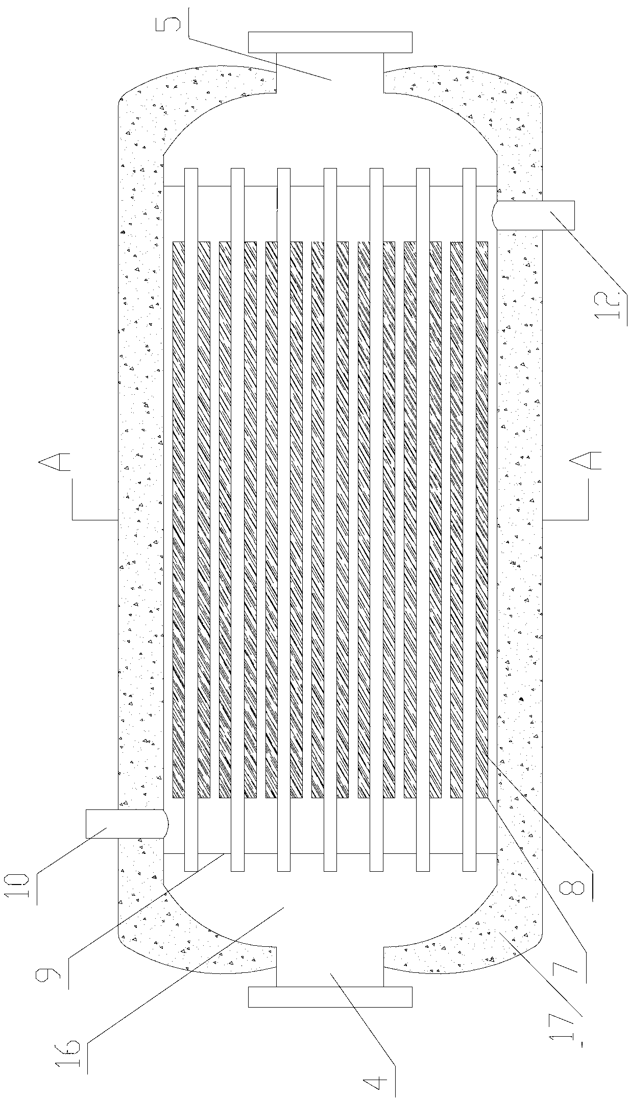
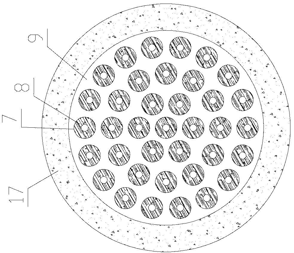
[0022] In the engine cold start preheating device of the present invention, a heat storage heat exchanger 3 is connected in parallel on the exhaust pipe 2 of the engine 1, and the inlet end 4 and the air outlet end 5 of the heat storage heat exchanger 3 are provided with first electronically controlled valves 6 To control whether the exhaust gas of the engine 1 passes through the heat storage heat exchanger 3; the heat storage heat exchanger 3 is used to store the exhaust heat of the engine 1. unit, each heat storage unit is a concentric casing 7 including two inner and outer tubes, and the phase change heat storage material 8 is packaged in the annular space between the inner and outer two tubes, and the packaging volume of the phase change heat storage material 8 should be less than that The volume of the space is such that there is an appropriate margin for the melting a...


PUM


Abstract

The invention discloses an engine cold-start preheating device. A heat storing heat exchanger (3) is in a parallel connection with an exhaust pipe (2) of an engine (1), the heat storing heat exchanger (3) is used for storing exhaust air waste heat of the engine (1), the heat storing heat exchanger (3) is in a columnar structure, a plurality of heat storing units are distributed in the heat storing heat exchanger (3), each heat storing unit is a concentric casing pipe (7) which comprises an inner pipe and an outer pipe, a phase change thermal storage material (8) is encapsulated in annular space between the inner pipe and the outer pipe, two ends of the inner pipe are welded on two flow guide plates (9) respectively, a hollow cavity for enabling cooling water of the engine (1) to flow through is formed by the two flow guide plates (9) and inner walls of the heat storing heat exchanger (3), and the inner walls of the heat storing heat exchanger (3) are located between the two flow guide plates (9). The engine cold-start preheating device has the advantages of being low in costs, small in size, efficient, energy-saving and convenient to popularize and use in a wide range.

Description

technical field [0001] The invention relates to the technical field of engine cold start preheating, in particular to an engine cold start preheating device. Background technique [0002] In recent years, with the increasing number of automobiles, automobile exhaust emissions have become an important source of pollution in the urban environment. The combustion process of fuel in an internal combustion engine is imperfect, and inevitably produces HC, CO, CO 2 and NO x and other pollutants. According to statistics, CO, HC and NO emitted from vehicle exhaust x The amount of these pollutants has accounted for 20%-50% of the total amount of these pollutants in the atmosphere, and the cold start emission pollution problem is an important aspect of automobile exhaust emission pollution, and the three-way catalytic converter cannot solve this problem during cold start. Especially in cold regions, where the winter temperature is tens of degrees Celsius below zero, most vehicles a...

Claims


Application Information

Patent Timeline
Patent Type & Authority Applications(China)
IPC IPC(8): F02N19/10F01N5/02
CPCY02T10/16Y02T10/12
Inventor 王永川李建新胡长兴郑皎吴勇平
Owner NINGBO INST OF TECH ZHEJIANG UNIV ZHEJIANG
Why Eureka
Try Eureka