Supercharge Your Innovation With Domain-Expert AI Agents!

Texturing a 3D modeled object

a 3d model and object technology, applied in the field of computer programs and systems, can solve the problems of deteriorating the texturing process, affecting the accuracy of the camera trajectory estimation, and being particularly sensitive to bias

Active Publication Date: 2018-07-03
DASSAULT SYSTEMES
View PDF27 Cites 10 Cited by
  • Summary
  • Abstract
  • Description
  • Claims
  • Application Information

AI Technical Summary

Problems solved by technology

Obviously, any bias on the camera pose translates onto the re-projection and deteriorates the texturing process.
Such a bias is usually particularly significant in the case of depth-map analysis methods.
It generally originates from a shift in synchronizing between the depth sensor and the RGB sensor, corrupting the camera trajectory estimation.
But it may also originate from: an outside shot from an independent camera whose relative position to the 3D model cannot be estimated with sufficient accuracy because there is no rigid dependency to the depth sensor; a noisy sensor, leading to inaccurate 3D models and camera poses; a drift in the 3D reconstruction process, leading to inaccurate 3D models; and / or distorted images leading to inaccurate texture mapping onto the 3D model.

Method used


Image

  • Texturing a 3D modeled object
  • Texturing a 3D modeled object
  • Texturing a 3D modeled object

Examples


Embodiment Construction

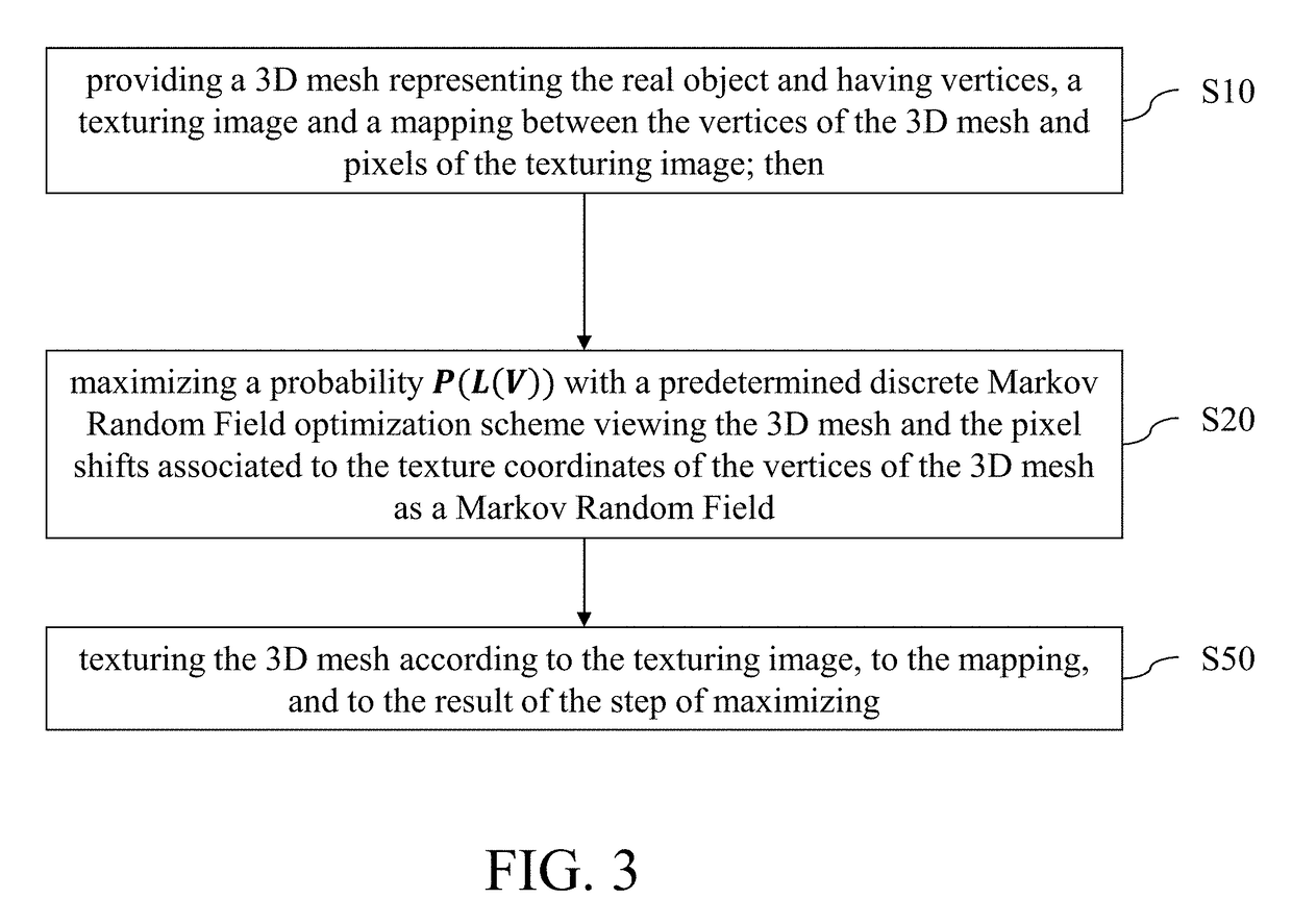
[0044]With reference to the flowchart of FIG. 3, it is proposed a computer-implemented method for designing a 3D modeled object representing a real object. Throughout the method, the 3D modeled object designates data that represent the real object in different ways: first its geometry via a 3D mesh, and then a textured geometry via the textured 3D mesh outputted by the method. The method comprises a step of providing S10 a 3D mesh representing the real object (the 3D mesh having notably vertices defined by 3D positions, e.g. but also edges linking the vertices, such as a triangular or a quad mesh), e.g. a 3D mesh without any texturing or with a texturing to be replaced by a new one (i.e. the texturing outputted by the method), a texturing image (a 2D view, e.g. an image such as a photograph, of the real object provided with values at pixel locations, of gray-level or of colors such as RGB values, being noted that the figures later illustrating examples of the method mainly show gray...


PUM


Abstract

A computer-implemented method for designing a 3D modeled object representing a real object comprises providing a 3D mesh representing the real object, a texturing image and a mapping between the vertices of the 3D mesh and pixels of the texturing image; then maximizing a probability P(L(V)) of the form:P⁡(L⁡(V))=1Z⁢exp⁡(-∑i=1n⁢⁢φi′⁡(L⁡(vi))-∑f∈ℱ⁢⁢ψf′⁡({L⁡(vi)}i∈f)).Maximizing is performed with a predetermined discrete Markov Random Field optimization scheme viewing the 3D mesh and the pixel shifts associated to the texture coordinates of the vertices of the 3D mesh as a Markov Random Field of energy −log(P(L(V)))−log(Z). The method then comprises texturing the 3D mesh according to the texturing image, to the mapping, and to the result of the maximizing.This provides an improved solution for designing a 3D modeled object a real object.

Description

RELATED APPLICATION[0001]This application claims priority under 35 U.S.C. § 119 or 365 to European Application No. 14306986.2, filed Dec. 10, 2014. The entire teachings of the above application(s) are incorporated herein by reference.FIELD OF THE INVENTION[0002]The invention relates to the field of computer programs and systems, and more specifically to a method, system and program for designing a 3D modeled object representing a real object.BACKGROUND[0003]A number of systems and programs are offered on the market for the design, the engineering and the manufacturing of objects. CAD is an acronym for Computer-Aided Design, e.g. it relates to software solutions for designing an object. CAE is an acronym for Computer-Aided Engineering, e.g. it relates to software solutions for simulating the physical behavior of a future product. CAM is an acronym for Computer-Aided Manufacturing, e.g. it relates to software solutions for defining manufacturing processes and operations. In such compu...

Claims


Application Information

Patent Timeline
Patent Type & Authority Patents(United States)
IPC IPC(8): G06T17/20G06T15/04G06F17/18G06T7/50G06T15/10G06F17/11G06F17/50
CPCG06T17/20G06F17/11G06F17/18G06F17/50G06T15/04G06T15/10G06T7/50G06T2207/20076G06T2207/10028G06F30/00
Inventor MEHR, ELOI
Owner DASSAULT SYSTEMES
Features
  • R&D
  • Intellectual Property
  • Life Sciences
  • Materials
  • Tech Scout
  • Unparalleled Data Quality
  • Higher Quality Content
  • 60% Fewer Hallucinations
Learn More