Supercharge Your Innovation With Domain-Expert AI Agents!

Flowchart generating method and flowchart generating apparatus based on QT 2D graphic view

a flowchart and graphic view technology, applied in the direction of visual/graphical programming, instrumentation, user interface execution, etc., can solve the problem of weak expansion of flowchart softwar

Active Publication Date: 2018-07-24
UBTECH ROBOTICS CORP LTD
View PDF1 Cites 0 Cited by
  • Summary
  • Abstract
  • Description
  • Claims
  • Application Information

AI Technical Summary

Benefits of technology

[0021]Since the application program of the QT graphic user interface may design the main process and the sub-module and may design the nodes of the modules, the modules may be easily called and the connection relationship may be easily established to design and develop the flowchart. Therefore, cross-platform development may be supported, less resource may be apply, and a third-part software may not be installed.

Problems solved by technology

Therefore, expansibility of the flowchart software is weak.

Method used


Image

  • Flowchart generating method and flowchart generating apparatus based on QT 2D graphic view
  • Flowchart generating method and flowchart generating apparatus based on QT 2D graphic view
  • Flowchart generating method and flowchart generating apparatus based on QT 2D graphic view

Examples


first embodiment

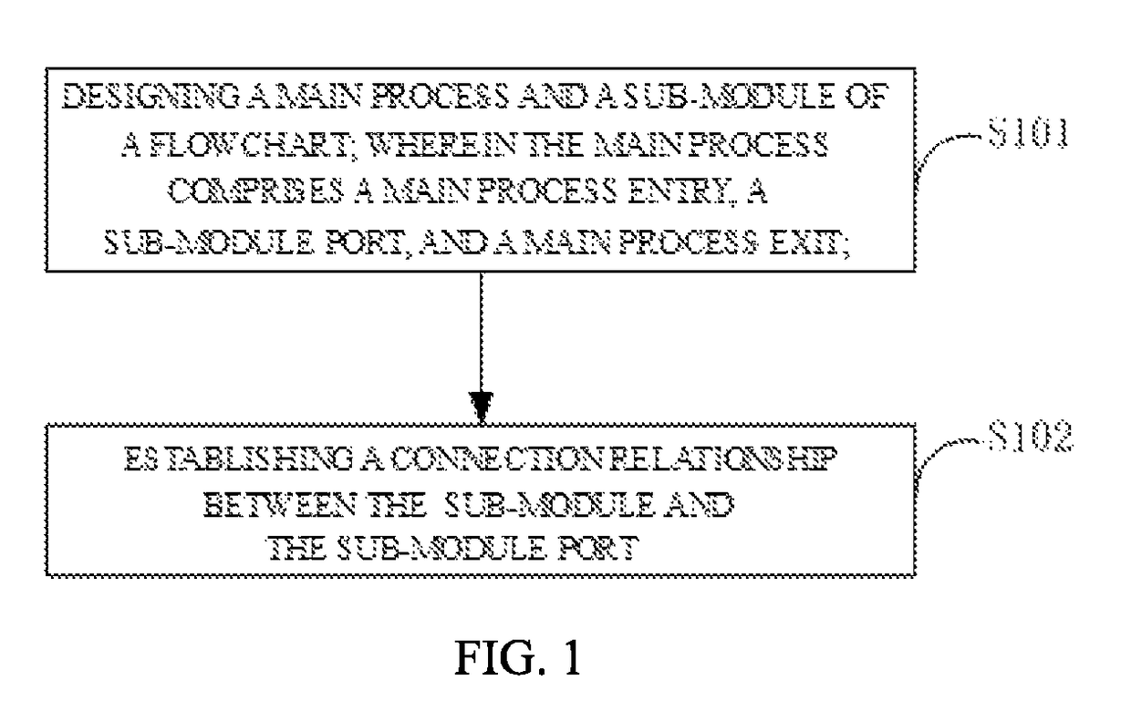
[0013]With reference to FIG. 1, the present disclosure provides a flowchart of a flowchart generating method. The flowchart generating method includes the following steps. In step S101, designing a main process and a first sub-module of a flowchart. The main process includes a main process start, a first sub-module node, and a main process end.

[0014]The flowchart is designed by an application program of a QT graphic user interface.

[0015]In the embodiment, the present disclosure is implemented by QT 2D graphic view architecture to design internal processes of a robot. The QT 2D graphic view architecture provides a manager that may support interaction of customized 2D graphic objects, and a view that may support a zooming operation and a rotating operation. The QT 2D graphic view architecture includes an event broadcasting architecture. The event broadcasting architecture may support a precise interacting ability of a scene manager, and may show variation of an object position or of a...

second embodiment

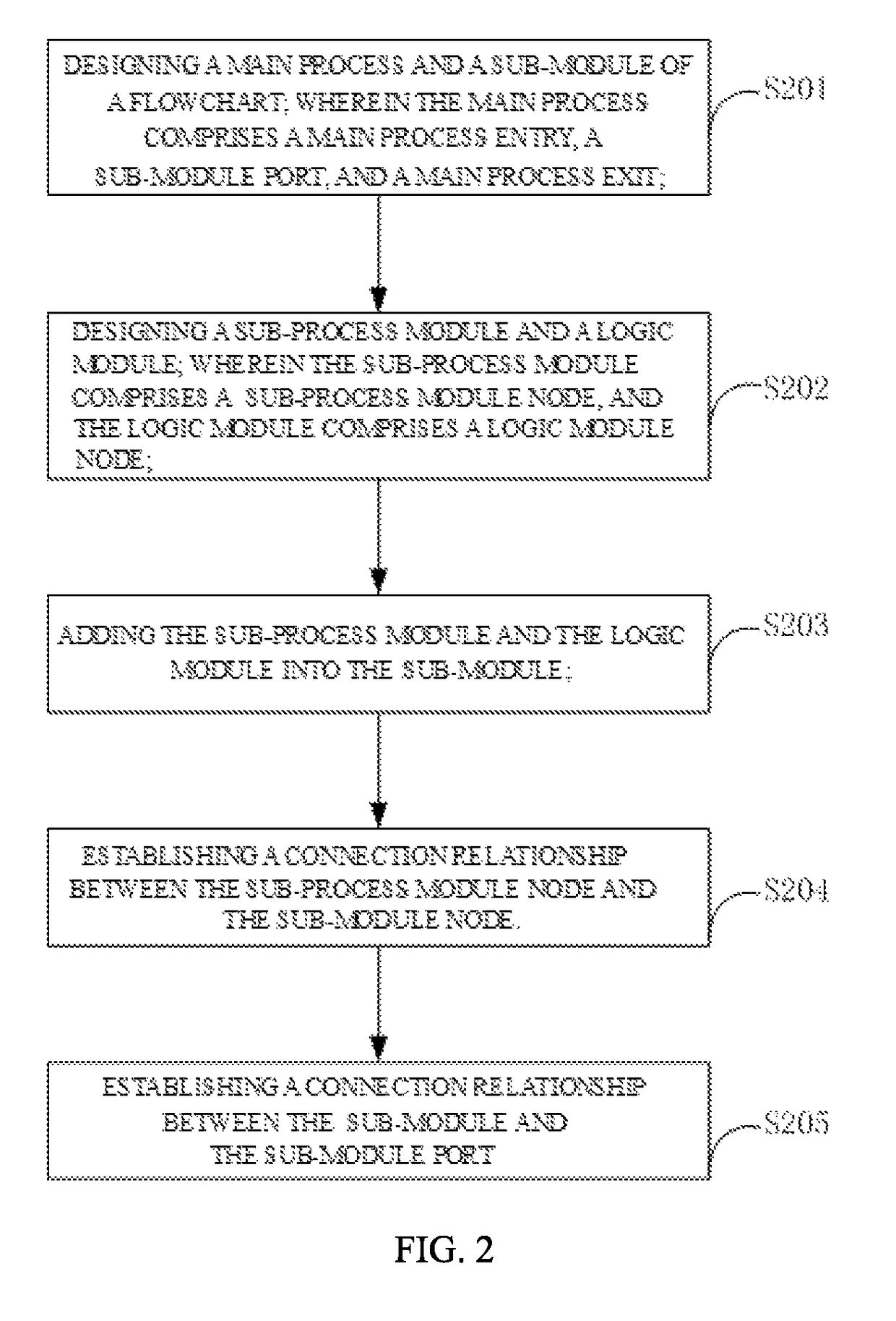
[0022]With reference to FIG. 2, the present disclosure provides a flowchart of a flowchart generating method. The flowchart generating method includes the following steps.

[0023]In step S201, designing a main process and a sub-module. The main process may include a main process start, a sub-module port, and a main process end.

[0024]The sub-module may include the sub-module node, and the sub-module node may include a sub-module entry node, a sub-module exit node, and a sub-module interrupted node.

[0025]In step S202, designing a sub-process module and a logic module. The sub-process module may include a sub-process module node, and the logic module may include a logic module node.

[0026]In step S203, adding the sub-process module and the logic module into the sub-module.

[0027]In step S204, establishing a connection relationship between the sub-process module node and the sub-module node.

[0028]The sub-process module and the logic module may be designed. The sub-process module may include...

third embodiment

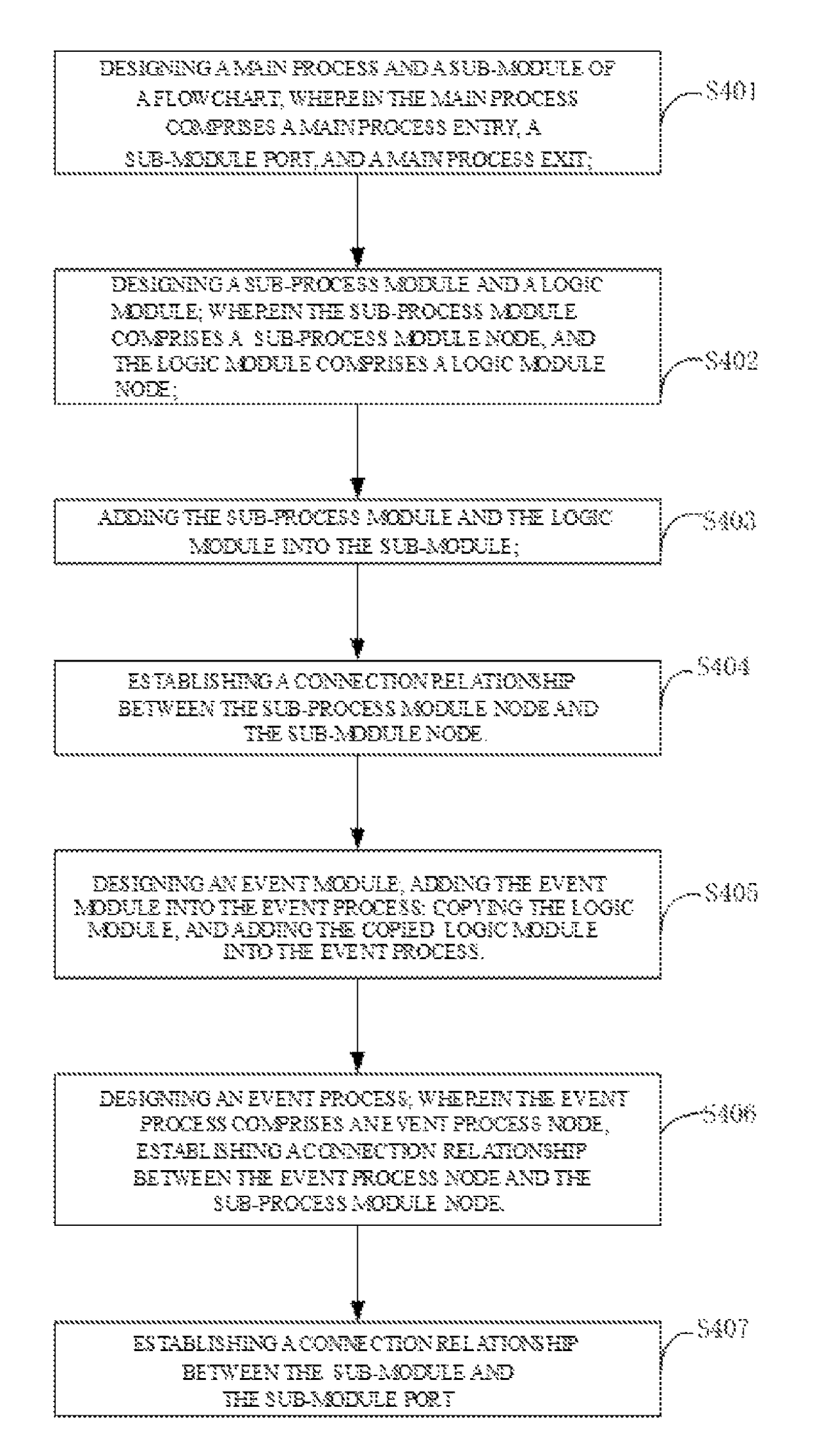
[0032]With reference to FIG. 3, the present disclosure provides a flowchart of a flowchart generating method. The flowchart generating method includes the following steps.

[0033]In step S301, designing a main process and a sub-module. The main process may include a main process start, a sub-module port, and a main process end.

[0034]The sub-module may include the sub-module node, and the sub-module node may include a sub-module entry node, a sub-module exit node, and a sub-module interrupted node.

[0035]In step S302, designing a sub-process module and a logic module. The sub-process module may include a sub-process module node, and the logic module may include a logic module node.

[0036]In step S303, adding the sub-process module and the logic module into the sub-module.

[0037]In step S304, establishing a connection relationship between the sub-process module node and the sub-module node.

[0038]In step S305, designing an event process. The event process may include an event process node, ...


PUM


Abstract

The present disclosure discloses a flowchart generating method including steps of: designing a main process and a sub-module of a flowchart; wherein the main process includes a main process start, a sub-module port, and a main process end. The sub-module includes a sub-module node, and the sub-module node includes a sub-module entry node, a sub-module exit node, and a sub-module interrupted node; establishing a connection relationship between the sub-module and the sub-module port. The present disclosure may support cross-platform development. Therefore, resources depended by the present disclosure may be reduced, and a third-part software may not be installed.

Description

CROSS REFERENCE TO RELATED APPLICATIONS[0001]This application claims priority to Chinese Patent Application No. 201611263418.7, filed Dec. 31, 2016, which is hereby incorporated by reference herein in its entirety.BACKGROUND[0002]1. Technical Field[0003]The present disclosure generally relates to a field of flowchart design, and particularly to a flowchart generating method and a flowchart generating apparatus.[0004]2. Description of Related Art[0005]A flowchart software based on Microsoft Foundation Classes (MFC) may provide an user to design and develop a flowchart. However, the flowchart software based on MFC may support Windows™ operating system, and may need to be supported by a third-part database. Therefore, expansibility of the flowchart software is weak. In order to support cross-platform development and to avoid installing a third-party software, a software to implement a flowchart generating method is needed to be developed.BRIEF DESCRIPTION OF THE DRAWINGS[0006]Many aspe...

Claims


Application Information

Patent Timeline
Patent Type & Authority Patents(United States)
IPC IPC(8): G06F9/44G06F8/30G06F8/34G06F8/35
CPCG06F8/34G06F8/35G06F8/313G06F9/451G06Q10/0633
Inventor XIONG, YOUJUNZHOU, ZHIPINGCHEN, LIN
Owner UBTECH ROBOTICS CORP LTD
Features
  • R&D
  • Intellectual Property
  • Life Sciences
  • Materials
  • Tech Scout
  • Unparalleled Data Quality
  • Higher Quality Content
  • 60% Fewer Hallucinations
Learn More