Device and method for conveying flat objects

a flat object and device technology, applied in the field of conveying technology, can solve problems such as uncontrollable conditions, errors in further processing, and the danger of individual products of objects displacing and achieve the effect of reducing the risk of displacing individual products of objects with respect to one another

Inactive Publication Date: 2018-08-07
FERAG AG
View PDF18 Cites 0 Cited by
  • Summary
  • Abstract
  • Description
  • Claims
  • Application Information

AI Technical Summary

Benefits of technology

[0024]A further object lies in further developing the device such that existing devices can be retrofitted without excessive effort or expense.
[0103]The invention has the advantage that differently thick objects can be transferred, without having to carry out settings at the pressing means every time. The pressing device moreover permits a simple and inexpensive retrofitting of existing devices, without the gripper conveyor and the conveying-away device themselves having to be rebuilt. The pressing device permits the assumption of a passive position and operational position, so that these can be applied in a selective manner.

Problems solved by technology

Thereby, the objects are situated in freefall for a brief period of time and are therefore in an uncontrolled condition.
This can lead to errors with the further processing.
If the object includes several products that are loosely grouped together, e.g., products that are laid onto one another or inserted into one another, then as was hitherto the case, there exists the danger of the individual products of the object displacing with respect to one another.
The lower the adhesive friction between the individual products, the greater is this danger.
This, in turn, limits the flexibility of the device with respect to the size, the type and the composition of the objects to be processed.
The described device, although permitting a release of the objects onto the conveying rest in a guided and controlled manner, the grippers, however, must be considerably modified for this, which for example entails the retrofitting of existing gripper conveyors at a considerable expense.
Moreover, the processing speed of the device is limited, since otherwise the mechanical loading upon the extended gripper limb, which is moved through the transfer region, becomes too great.
Thus, the conveying speeds are low when starting the device from standstill or on stopping the device over a certain period of time, which in particular is characterised by an acceleration or braking ramp.
A starting-up of the device, however, is not only necessary on assuming operational production, but also after interruptions due to malfunctioning.
A stoppage of the installation accordingly not only entails the finishing of the production, but can also be due to a production disturbance.
Moreover, it can occur that the device must be operated at a lower speed over a certain period of time or over the complete duration of the production for various reasons, for example due to extremely complex objects being processed.

Method used


Image

  • Device and method for conveying flat objects
  • Device and method for conveying flat objects
  • Device and method for conveying flat objects

Examples


Embodiment Construction

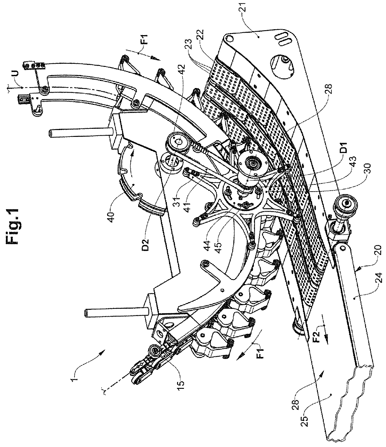
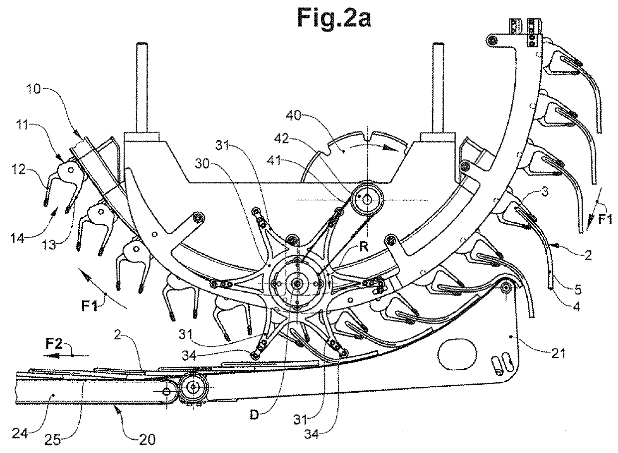
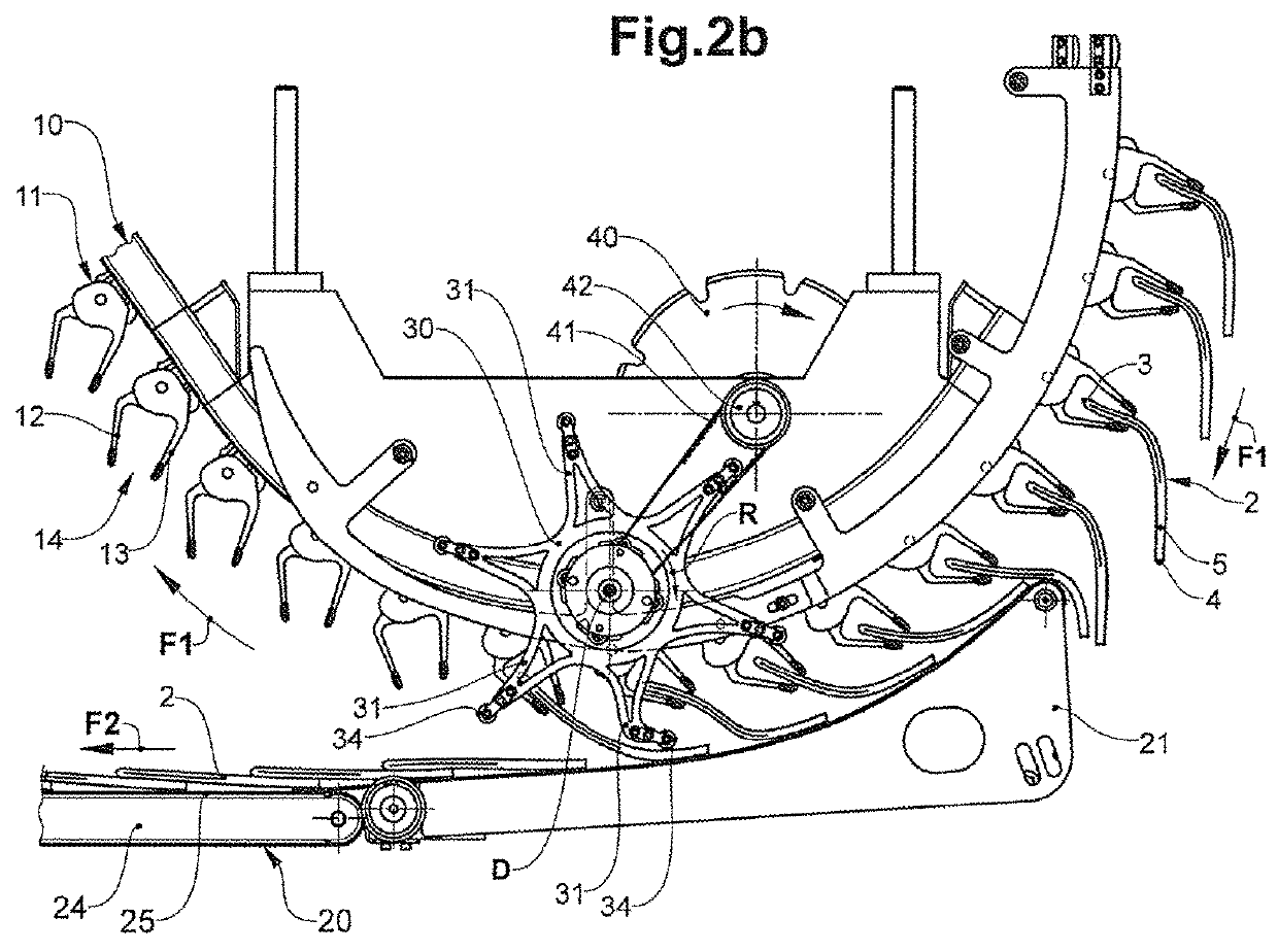
[0115]FIGS. 1, 2a-2d and 3 show a device 1 according to the invention and according to a first embodiment.

[0116]The device 1 includes a gripper conveyor 10 with a plurality of grippers 11, which are moved along a gripper conveying path U and which are distanced to one another.

[0117]The device 1 further includes an onward conveying device 20 with a conveying rest 28. The gripper conveyor 10 and the onward conveying device 20 form a transfer region T, in which objects 2, 2′ are released from the grippers 11 of the gripper conveyor 10 and are deposited onto the conveying rest 28 of the onward conveying device 20.

[0118]The conveying rest 28 of the onward conveying device 20, in the transfer region T, is arranged below the grippers 11 of the gripper conveyor 10. The conveying path U of the gripper conveyor runs arcuately towards the transfer region T from the top to the bottom towards the conveying rest and subsequently to the transfer region T runs arcuately from the bottom to the top a...


PUM

PropertyMeasurementUnit
flexibleaaaaaaaaaa
contact pressureaaaaaaaaaa
geometric rotationaaaaaaaaaa

Abstract

A device for conveying and transferring flexible, flat objects with a gripper conveyor including a plurality of grippers that are movable along a conveying path in a conveying direction, and further with a conveying-way device that forms a conveying rest that, in a transfer region, is arranged below the conveying path such that objects that are released from grippers in the transfer region are deposited onto the conveying rest. The device includes a pressing circulatory device that acts upon the transfer region and has a plurality of outwardly directed pressing arms. The pressing circulatory device is designed, in the transfer region, to press the objects to be transferred with the pressing arms onto the conveying rest such that the objects can be deposited onto the conveying rest in a guided and controlled manner.

Description

BACKGROUND OF THE INVENTION[0001]Field of the Invention[0002]The present invention lies in the field of conveying technology and relates to a device and to a method for conveying and transferring flexible, flat objects. The device includes a gripper conveyor with a plurality of grippers that are movable in a conveying direction along a conveying path, moreover a conveying-away device with a conveying rest that is arranged in a transfer region below the conveying path of the gripper conveyor such that objects released by grippers in the transfer region are deposited onto the conveying surface. The device further includes pressing devices that are designed in order, in the transfer region, to the press the objects to be transferred, onto the conveying rest such that the objects are deposited onto the conveying rest in a guided and controlled manner.[0003]Description of Related Art[0004]Increasingly more complex, flexible flat objects are conveyed and / or processed in another manner in ...

Claims


Application Information

Patent Timeline
Patent Type & Authority Patents(United States)
IPC IPC(8): B65H5/08B65H29/66B65H29/24B65H5/24B65H5/16B65H29/16B65H29/00
CPCB65H5/085B65H5/16B65H5/24B65H29/003B65H29/16B65H29/242B65H29/6609B65H2405/552B65H2404/1521B65H2301/44735B65H2301/44732B65H2301/44712B65H2301/446B65H2220/02B65H2220/01
Inventor DAX, ROMAN
Owner FERAG AG
Why Eureka
Try Eureka