Energy optimized imaging system with synchronized dynamic control of directable beam light source and reconfigurably masked photo-sensor

a technology of energy-efficient imaging and directable beam light source, which is applied in the field of energy-optimized imaging system, can solve the problems of inefficient power inefficient practice, and inability to optimize the energy consumption of current-use devices, so as to achieve more optical components, more computation, and far more expense.

Pending Publication Date: 2022-02-03
CARNEGIE MELLON UNIV +1
View PDF34 Cites 0 Cited by
  • Summary
  • Abstract
  • Description
  • Claims
  • Application Information

AI Technical Summary

Benefits of technology

[0007]By synchronizing control of both a light source that has the ability to illuminate a specific area(s) along with a photosensor having a configurable mask having the ability to mask specific pixels, this invention can perform numerous imaging techniques that are either not possible with current technology, or are possible with current technology but would require far more optical components, far more expense, far more computation, and / or far more power consumption.
[0008]This invention can demonstrate several never-seen-before capabilities. For instance, live structured-light video of very bright scenes can be captured, even, for example, a light bulb that is on. The invention can also capture epipolar-only and indirect-only live video with optimal energy efficiency. The invention can measure the 3D shape of objects in challenging conditions, such as strong indirect light, strong ambient light, and smoke while using a low-power projector as the light source. Also, the invention can record live video from the point of view of a projector, rather than a photosensor.

Problems solved by technology

However, these devices in the currently used configurations are also inefficient in their power consumption.
In this ubiquitous configuration, the light source is always turned on, and, while the energy efficiency of light sources have greatly increased over time, having the light source always turned on is still a major source of power consumption.
This practice is not energy efficient, however, due to the fact that photons that are being generated are simply blocked within the system.

Method used


Image

  • Energy optimized imaging system with synchronized dynamic control of directable beam light source and reconfigurably masked photo-sensor
  • Energy optimized imaging system with synchronized dynamic control of directable beam light source and reconfigurably masked photo-sensor
  • Energy optimized imaging system with synchronized dynamic control of directable beam light source and reconfigurably masked photo-sensor

Examples


Embodiment Construction

[0013]A widely known truth in the field of image capture is that to optimally capture images with the most detail and least noise, the light throughput between the light source and the photosensor must be optimized. This invention implements this maxim while at the same time allowing for selective blocking of light paths between the light source and photosensor. The system topology that results from this optimization also allows for never-seen-before imaging techniques and energy efficiency.

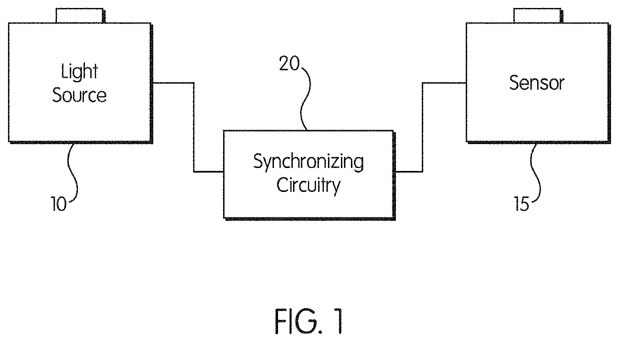
[0014]There are three main parts to the invention as currently implemented, interconnected as shown in FIG. 1: a directable light source 10, a sensor 15 and, crucial to this invention, a synchronizing controller 20 that synchronizes the active region of sensor 15 to the beam direction of light source 10 in accordance with an optimizing equation, discussed below.

[0015]As used herein, the term “directable light source” is a controllable light source that emits different amounts of light in differen...


PUM


Abstract

An energy optimized imaging system that includes a light source that has the ability to illuminate specific pixels in a scene, and a sensor that has the ability to capture light with specific pixels of its sensor matrix, temporally synchronized such that the sensor captures light only when the light source is illuminating pixels in the scene.

Description

RELATED APPLICATIONS[0001]This application is a divisional application filed under 35 U.S.C. § 121 of U.S. patent application Ser. No. 16 / 516,664, filed Jul. 19, 2019, which is a continuation of U.S. patent application Ser. No. 15 / 545,391, filed Jul. 21, 2017, which is a filing under section 371 of PCT Application No. PCT / US16 / 17942, filed Feb. 15, 2016, which claims the benefit of U.S. Provisional Patent Application No. 62 / 176,352, filed Feb. 13, 2015.GOVERNMENT RIGHTS[0002]This invention was made with government support under National Science Foundation No. IIS317749 and Army / ARO No. W911NF-10-2-0016. The government has certain rights in this invention.BACKGROUND OF THE INVENTION[0003]When an image is captured under controlled lighting, the power of the light source has great impact on the result. All things being equal, brighter sources will send more photons to the sensor during an exposure, producing a brighter and less noisy image.[0004]The brightness of the source, however, i...

Claims


Application Information

Patent Timeline
Patent Type & Authority Applications(United States)
IPC IPC(8): G01B11/25G03B21/20H04N13/271H04N9/31H04N5/30
CPCG01B11/2513G01B11/2518G01B11/2545G06T17/00H04N13/271H04N9/3129H04N5/30G03B21/2033G01S17/89G01S17/42G06T7/521G03B7/16G03B17/54G03B15/02G01S7/4817G01S17/10H04N23/60H04N23/65H04N23/74
Inventor NARASIMHAN, SRINIVASAACHAR, SUPREETHO'TOOLE, MATTHEWKUTULAKOS, KIRIAKOS NEOKLIS
Owner CARNEGIE MELLON UNIV
Why Eureka
Try Eureka