Gapless screw rotor device

a screw-rotor and screw technology, applied in the direction of liquid fuel engines, machines/engines, rotary/oscillating piston pump components, etc., can solve the problems of inability to meet the needs of the user, so as to reduce gaps, minimize recirculation, and maximize thermodynamic efficiency and volumetric efficiency

Inactive Publication Date: 2006-03-07
IMPERIAL RES
View PDF23 Cites 14 Cited by
  • Summary
  • Abstract
  • Description
  • Claims
  • Application Information

AI Technical Summary

Benefits of technology

[0028]It is an advantage of the present invention to maximize the thermodynamic efficiency and the volumetric efficiency in a screw rotor system by several means, such as reducing gaps, minimizing recirculation within the screw rotor housing, reducing shock waves within the screw rotors, reducing entropy, and reducing sliding friction between the male rotor and the female rotor. It is also an advantage of the present invention that it is readily producible. The designs can be rather simple and still maintain a good sealing relationship. Therefore, the present invention does not suffer from an overly complicated design that is difficult to machine or to otherwise manufacture. It is another advantage of the present invention that it can reduces and nearly eliminate backlash. It is yet another advantage of the present invention that it can reduce the cost of manufacturing screw rotor compressors and, due to its increased thermodynamic and volumetric efficiencies, it can also reduce the cost of ownership for screw rotor compressors. It is a further advantage that the present invention provides economy, efficiency and speed of assembly in manufacturing, and also reduces the cost of component assembly and the packaging costs of the product. It is yet a further advantage of the present invention in that the screw rotor system can be designed as a modular device that can be replaced with a cartridge-type system or completely integrated into a particular product. To the extent that various components of the screw rotor system are manufactured separately, and then shipped to an assembler for fixation of additional components & / or for further assembly into final products, the modular aspects of the present invention improve the efficiency and economy of assembly. In comparison to bladed compressors and turbines, the present invention is much stronger, more economical, and provides more compact components.
[0029]Accordingly, no earlier design follows the design methodology of the present invention which, as discussed below, can effect a compete seal regardless of the types of lines, straight or arcuate. The present invention can also effect a complete seal for multiple pitched rotors. The new design method is even so robust that it produces geometries that can even effect a complete seal multiple areas simultaneously, including areas between the male rotor and the female rotor as well as between the rotors and the housing.
[0030]Now that this design problem has been identified, it will be appreciated that by viewing the threads and grooves in the third dimension and making accommodations for the third dimension in the design process, there is an additional degree of design freedom which permits intermeshing screw rotors to be designed without leak pathways or other gaps between the male rotor and the female rotor and between the rotors and the housing, including the blow-hole at the transition region and discussed above. Once the design problem is viewed in the third dimension, it becomes clear that there should be a way to eliminate the blow-hole gap while maintaining the seals between the thread and groove. Accordingly, the present invention teaches that, to eliminate the blow-hole gap, the sealing region should extend completely from the housing's front cusp to its back cusp. Finally, when the design choices are again translated into planar design methodology, the creation of the designs becomes much less difficult than many of the planar design methodologies that are increasingly being suggested as the only way to increase the efficiencies.
[0031]Also disclosed herein is an example of the inventive method for designing entire families of the present invention's threads and corresponding grooves. The new thread and groove design results in a high-efficiency screw rotor system which is heretofore unknown in the prior art. The features of the invention result in an advantage of improved thermodynamic efficiency and improved volumetric efficiency of the screw rotor device. Tests on the prototype design show that the thermodynamic efficiency are likely to reach greater than 85% and may even exceed 90%. The present invention is seminal because it is the first screw rotor to achieve these efficiencies over a wide range of rotor speeds.
[0032]Further features and advantages of the present invention, as well as the structure and operation of various embodiments of the present invention, are described in detail below with reference to the accompanying drawings.

Problems solved by technology

However, an involute for a gear tooth is primarily designed for strength and to prevent lock-up as teeth mesh with each other and are not necessarily optimum for the circumferential sealing of rotors within a housing.
Although adiabatic efficiency and volumetric efficiency are different performance parameters, a number of screw rotor features can affect both of these efficiencies.
Such performance characteristic could be caused by thermal expansion of the rotors, machining tolerances, and even the material properties of the rotors, which can result in intermittent contact between the rotors and the sides of the housing or between the rotors themselves.
Such inherent leaks would occur even when the tolerances are perfected, i.e., zero thermal expansion, perfect machining tolerances, and a perfectly smooth finished material.
These leak pathways result in losses that adversely affect both the thermodynamic efficiency and the volumetric efficiency of screw rotors.
Accordingly, leak pathways are some of the most important losses to consider for the performance of screw rotors when the screw rotors are being designed because these losses negatively affect both thermodynamic efficiency and volumetric efficiency.
In fact, it is a common belief by the designers, manufacturers and users of screw rotors that it is impossible to eliminate some of the leaks in a screw rotor system.
However, there remains a need for better methodologies for designing screw rotor profiles that account for machining constraints, thermal expansion and material tolerances, as well as mechanical efficiencies, and that also eliminate any inherent leak pathway from the design process, even though it is presently considered impossible.
In comparison, when the leak pathway remains an inherent feature of the rotor profiles, the designer must first minimize the leak pathway using more complex designs that are harder and costlier to manufacture and then changes to the design are limited by the complexity of the design, machining and other manufacturing capabilities and thermal expansion requirements.
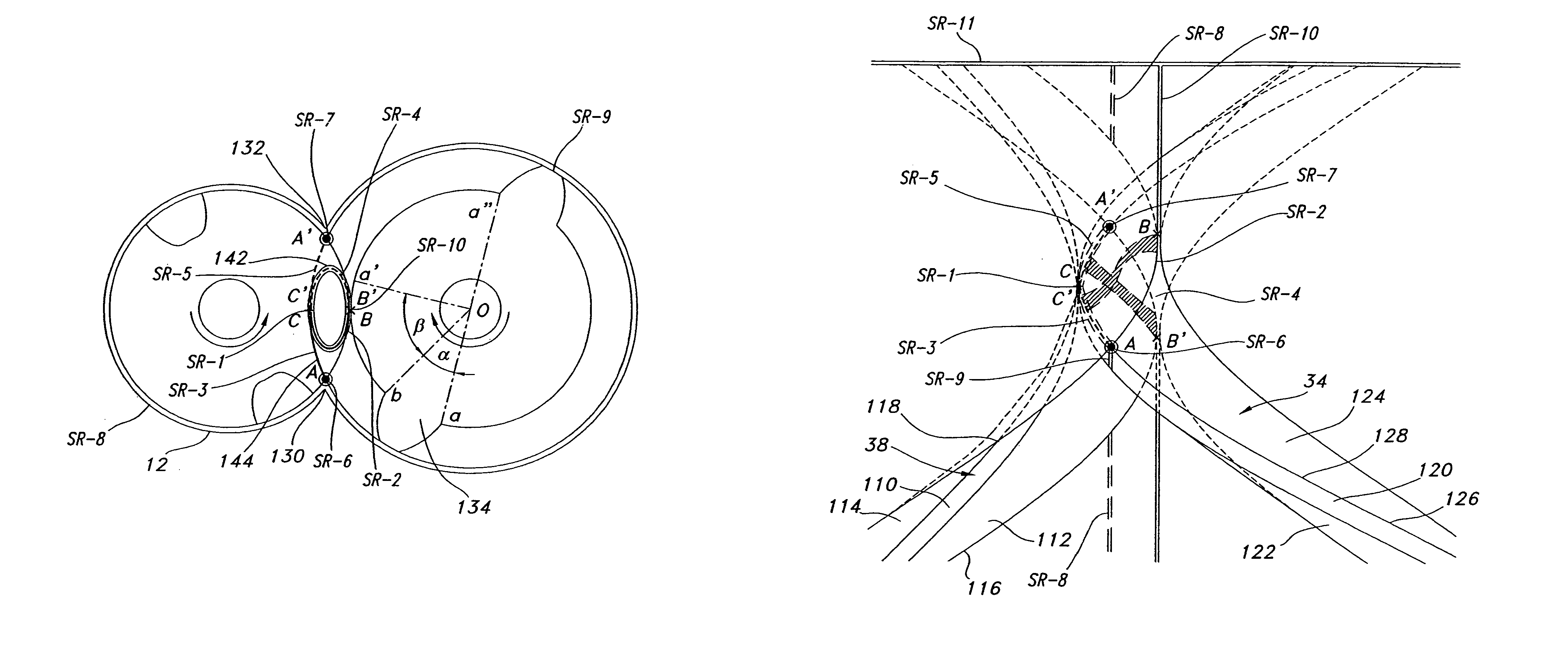
Leak pathways are generally caused by internal leakage between the rotors and the housing and between the rotors themselves and result in volumetric losses and thermodynamic losses due to recirculation of the working fluid within the rotors.
In this transition, a gap is formed between the meshing threads and the housing, causing leaks of the working fluid through the gap in the sealing surfaces and resulting in less efficiency in the rotor system.
A number of arcuate profile designs improve the seal between rotors and may reduce the gap in this transition region but these profiles still retain the characteristic gear profile with tightly spaced teeth around the circumference, resulting in a number of gaps in the transition region that are respectively produced by each of the threads.
Some pumps minimize the number of threads and grooves and may only have a single acme thread for each of the rotors, but these threads have a wide profile around the circumferences of the rotors and generally result in larger gaps in the transition region.
Until now, screw rotor expanders, compressors and pumps have had similar fundamental flaws.
While it is clear from the images of the Krigar design that there definitely were sealing issues, especially between the threads and the grooves, and Krigar appears to be more directed to radial flow, the Lysholm conclusion that the Krigar design could not perform any compression with only the 2×2 configuration is flawed.
Additionally, since the rotor profiles are designed according to the traditional gear profile design methods, these rotors are usually limited in the types of arcuate lines that can be used to effect the seal.
When the third dimension is accounted for in prior art design methodologies, it is typically limited to standard helix angle definitions that have been developed for ordinary screws, i.e., fastening screws.
Such an approach fails to truly account for and does not take advantage of the third dimension.
The planar design methodologies fail to apply the function of the helix angle with respect to the radius, resulting in the profiles with leak pathways discussed above.
In one aspect, the planar design methods are unnecessarily restrictive because they only take advantage of two-dimensional space to overcome the limitation that the threads must not lock-up in the grooves.
In another aspect, the planar design methods are not restrictive enough because when the profiles are expanded into three-dimensional space, the profiles have three-dimensional leak pathways.
More generally, similar fundamental flaws in the prior art designs and their respective methodologies can be traced back to their failure to accommodate for and use the additional degree of design freedom provided by the third dimension.
Such rounded edges and ridges cannot possibly seal between the rotors and the housing when the thread and groove begin meshing with each other.
In some designs, the gap can be even larger, such as in screw rotors that have a different number of threads and grooves, i.e. not the same number of threads as grooves, and the loss in pressure to the low pressure side causes the thermodynamic efficiency to drop.
Additionally, by failing to take advantage of the third dimension in the design of the thread and groove, the prior art design methods have failed to optimize the basic screw rotor design or improve the screw rotor efficiencies to their full potential.
In an attempt to compensate for this unwitting failure to take advantage of the third dimension, the prior art designs have increasingly become more complex over the years without offering much improvement in the thermodynamic efficiency of the rotor system.
As evidence of the failure to appreciate volumetric design methodologies as an alternative to traditional gear design methods combined with traditional fastener screw methods, these planar design methodologies increasingly led to these more complex screw rotor designs as machining and other manufacturing methods improved over the years and permitted the increasing complexity.
Additionally, these increasingly complex screw rotor profile designs, which need such improved manufacturing methods, support the conclusion that the failure to take advantage of the third dimension has been an unwitting failure because volumetric design methodologies actually permit much more simplified designs which can be less complex to manufacture than profiles created using the planar design methodologies.

Method used


Image

  • Gapless screw rotor device
  • Gapless screw rotor device
  • Gapless screw rotor device

Examples


Embodiment Construction

[0060]Referring to the accompanying drawings in which like reference numbers indicate like elements, FIGS. 1 and 9 illustrate an axial cross-sectional schematic view of a screw rotor device 10. The screw rotor device 10 generally includes a housing 12, a male rotor 14, and a female rotor 16. The housing 12 has an inlet port 18 and an outlet port 20. The inlet port 18 is preferably located at the gearing end 22 of the housing 12, and the outlet port 20 is located at the opposite end 24 of the housing 12. The male rotor 14 and female rotor 16 respectively rotate about a pair of substantially parallel axes 26, 28 within a pair of cylindrical bores 30, 32 extending between ends 22, 24.

[0061]In the preferred embodiment, the male rotor 14 has at least one pair of helical threads 34, 36, and the female rotor 16 has a corresponding pair of helical grooves 38, 40. The female rotor 16 counter-rotates with respect to the male rotor 14 and each of the helical grooves 38, 40 respectively interme...


PUM


Abstract

A screw rotor device has a housing with an inlet port and an outlet port, a male rotor with helical threads, and a female rotor with helical grooves. The helical threads and helical grooves are designed to eliminate the blow hole leak pathway for multiple-pitch screw rotor devices as well as single-pitch screw rotor devices. The male rotor has a pair of helical threads with a phase-offset aspect, and the female rotor has a corresponding pair of helical grooves. The female rotor counter-rotates with respect to the male rotor and each of the helical grooves respectively intermeshes in phase with each of the helical threads. The phase-offset aspect of the helical threads is formed by a pair of teeth bounding a toothless sector.

Description

CROSS-REFERENCE TO RELATED APPLICATIONS[0001]This application is a continuation-in-part of U.S. application Ser. No. 10 / 283,421, filed on Oct. 29, 2002 and issued as U.S. Pat. No. 6,719,547 on Apr. 13, 2004, which is a continuation-in-part of U.S. application Ser. No. 10 / 013,747, filed on Oct. 19, 2001 and issued as U.S. Pat. No. 6,599,112 on Jul. 29, 2003.[0002]This application is also related to the subject matter in co-pending U.S. Application Ser. No. 10 / 283,422, filed on Oct. 29, 2002 and issued as U.S. Pat. No. 6,719,548 on Apr. 13, 2004, which is hereby incorporated by reference into the present invention disclosure. This application is also related to the subject matter in co-pending U.S. application Ser. No. 10 / 764,195, patent application filed on Jan. 23, 2004, which is also a continuation of U.S. application Ser. No. 10 / 283,421 and is also hereby incorporated by reference into the present invention disclosure.STATEMENT REGARDING FEDERALLY SPONSORED RESEARCH OR DEVELOPMENT...

Claims


Application Information

Patent Timeline
Patent Type & Authority Patents(United States)
IPC IPC(8): F01C1/16F01C1/00F01C1/08F04C18/08F04C18/16F04C29/00
CPCF01C1/084F01C1/16F04C29/0028F04C18/084F04C18/16
Inventor HEIZER, CHARLES K.
Owner IMPERIAL RES
Why Eureka
Try Eureka