Eureka AIR delivers breakthrough ideas for toughest innovation challenges, trusted by R&D personnel around the world.

Connector assembly for attaching a cable to an electrical device

Active Publication Date: 2018-08-28
ARDENT CONCEPTS INC
View PDF9 Cites 1 Cited by
  • Summary
  • Abstract
  • Description
  • Claims
  • Application Information

AI Technical Summary

Benefits of technology

The present invention is a connector assembly for terminating cables to an electrical device without the need for tools or extra connectors. The assembly uses compliant contact technology and a spring-loaded interface to provide a secure connection to the device. The interface and boss / cable assembly reciprocate freely within a cylindrical sleeve with the interface towards the device. The assembly includes a barrel with pawls that engage with alignment posts on the device for easy installation. The assembly is designed for a specific range of PCB thicknesses and can be easily modified. The invention allows for a quick and easy connection between cables and the device without the need for additional components or tools.

Problems solved by technology

The SMA connectors, while being generally the same impedance environment as the cable, have impedance mismatches that cause high-frequency attenuation at the point of interface between the cable and the connector and between the connector and its working environment, like a PCB.
Additionally, these cable terminations often require through holes in PCBs for mounting and consequently can make it difficult to design the best possible controlled-impedance environment.
Solder-down versions exist, but they cannot be removed and reused after being installed.
Allowances must be made for fingers or for the torque wrench when spacing multiple connectors on a board, thereby requiring a substantial amount of board real estate to terminate, and decreasing the density capability of connections.

Method used


Image

  • Connector assembly for attaching a cable to an electrical device
  • Connector assembly for attaching a cable to an electrical device
  • Connector assembly for attaching a cable to an electrical device

Examples


Embodiment Construction

[0050]The present application hereby incorporates by reference in their entireties U.S. Provisional Patent Application Nos. 62 / 396,448 and 62 / 436,160, on which this application is based.

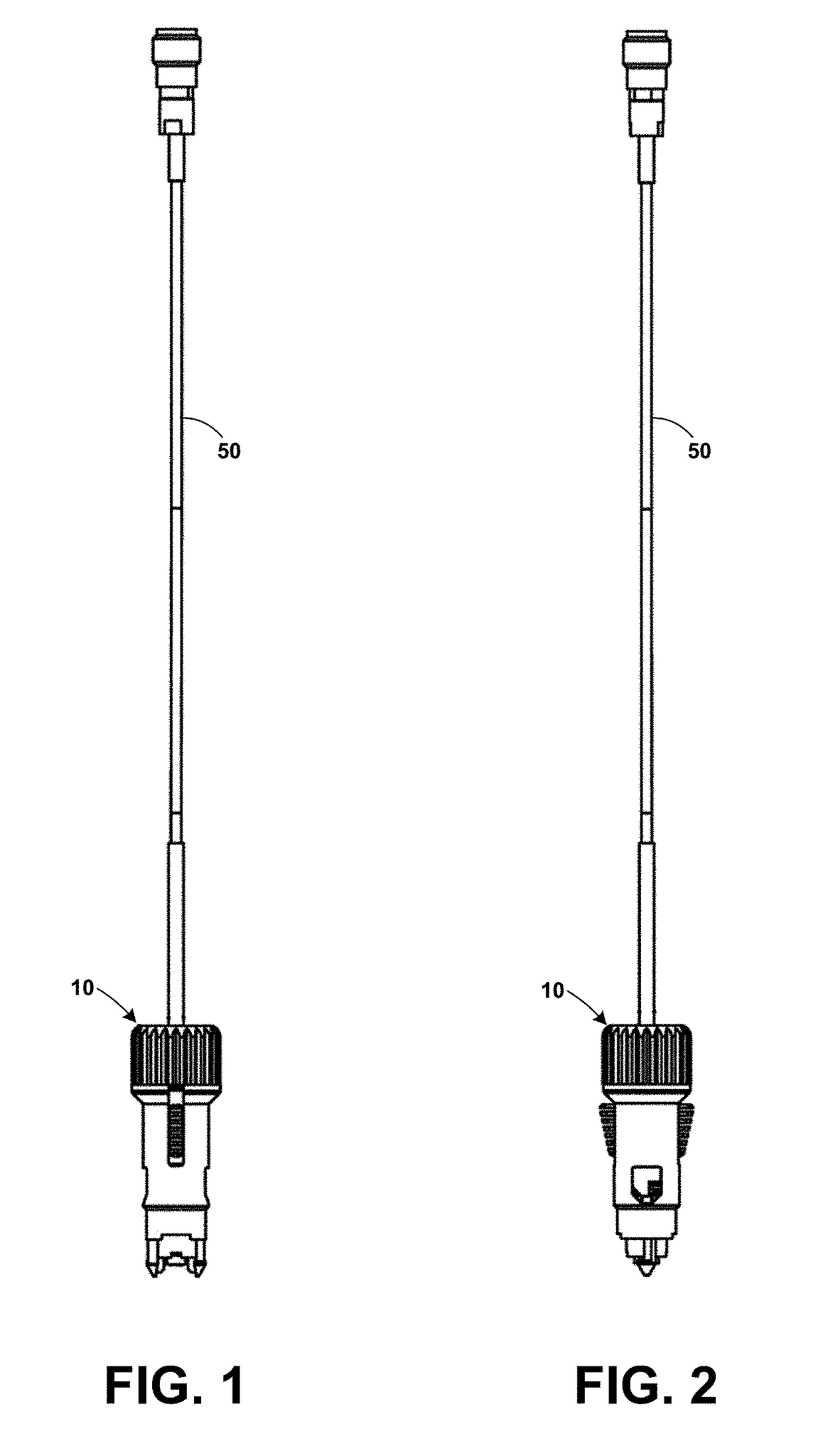
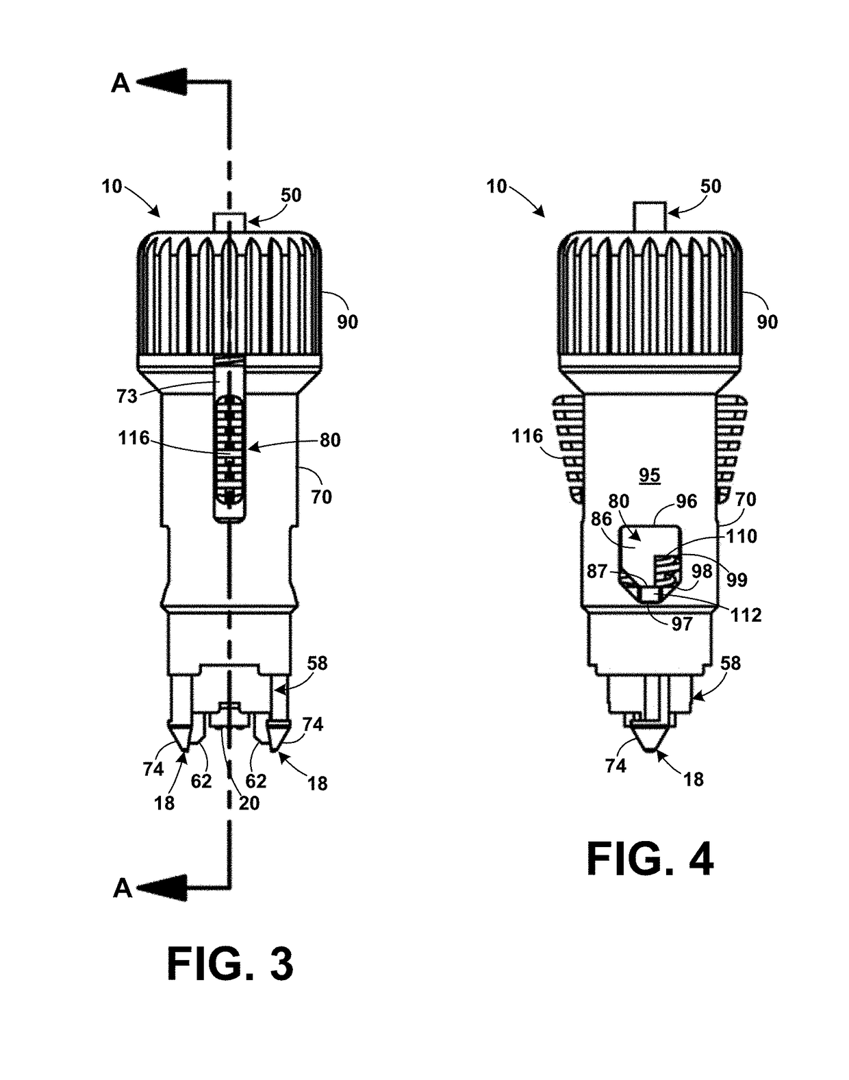
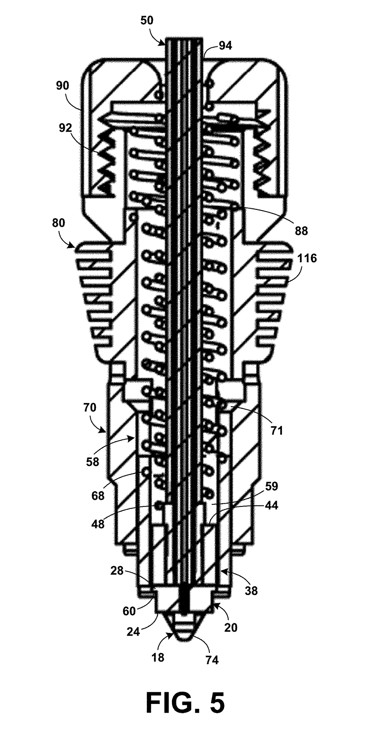
[0051]The present invention, shown in FIGS. 1-10, is a connector assembly for terminating a cable to an electrical device, such as a printed circuit board (PCB), without screws or other latching hardware that cannot be removed without using tools. The term, PCB, in the remainder of the present specification is intended to include all electrical devices to which the termination of the present invention can attach. The terms “proximal” and “distal” in the present specification refer to directions toward the PCB and the away from the PCB, respectively. For example, the proximal end of the connector assembly is the end that attaches to the PCB.

[0052]The connector assembly 10 of the present invention also does not require extra connectors to be soldered to the PCB 12 before connectors can be mated. The co...


PUM


Abstract

A connector assembly for terminating cables to a PCB. An interface of compliant contacts within in a cylindrical disk of dielectric material and a boss with the cable attached reciprocate within a cylindrical sleeve with the interface toward the PCB. Springs bias the interface and boss toward the PCB. The sleeve, interface, boss / cable assembly, and springs are slid into a barrel that has a pair of pawls extending paraxially from the proximal end. The pawls combine with paraxial alignment fingers on the sleeve. In the unattached position, the circular alignment posts fit into round PCB holes. As the connector is pushed toward the PC, the sleeve contacts the PCB and stops, but the barrel continues until it is free to rotate to an attached position where the pawl fingers slide under the PCB. An optional locking mechanism locks the barrel in the attached position.

Description

STATEMENT REGARDING FEDERALLY SPONSORED RESEARCH OR DEVELOPMENT[0001]Not ApplicableREFERENCE TO A SEQUENCE LISTING, A TABLE, OR A COMPUTER PROGRAM LISTING COMPACT DISK APPENDIX[0002]Not ApplicableBACKGROUND OF THE INVENTION1. Field of the Invention[0003]The present invention relates to electrical cable attachments to circuit boards and other planar electrical devices (PCB), more particularly, to quickly, temporarily terminating an interconnect to a PCB with the mating pressure needed to make a good connection.2. Description of the Related Art[0004]One purpose of a cable termination is to provide a separable electrical interconnection between a cable and a PCB or other planar electrical device. The characteristic of separability means that the cables are not interconnected by permanent mechanical means, such as soldering or bonding, but by temporary mechanical means.[0005]Currently, cables are terminated using a conventional-type connector which is also controlled-impedance, like an ...

Claims


Application Information

Patent Timeline
IPC IPC(8): H01R13/24H01R13/622H01R12/71H01R13/652H01R13/08H01R12/70
CPCH01R12/716H01R13/652H01R13/622H01R12/7005H01R13/08H01R12/7029H01R12/7052H01R12/714H01R13/2421
Inventor VINTHER, GORDON ADIAZ, SERGIODIDONNA, JOSEPH F
Owner ARDENT CONCEPTS INC
Why Eureka
Eureka Blog
Learn More