Flying car or drone

a flying car and drone technology, applied in the field of flying cars or drones, can solve the problems of increasing traffic congestion, frustration for those confined to land vehicles, and only very limited mobility of helicopters on the ground, so as to improve the performance and efficiency of the rotor/propeller, improve the safety of passengers, and improve the effect of rotor/propeller performan

Inactive Publication Date: 2018-09-25
RADU BOGDAN
View PDF58 Cites 14 Cited by
  • Summary
  • Abstract
  • Description
  • Claims
  • Application Information

AI Technical Summary

Benefits of technology

[0025]An advantage of the invention is that it enables independent control of the individual rotors without complicated mechanical force-distribution couplings.
[0026]Another advantage of the invention is that the rotor / propeller can be adapted to current flight conditions or the current airflow speed in the rotor plane, thus improving the performance and efficiency of the rotor / propeller.
[0027]Yet another advantage is that the invention enables usage of the side unpacked rotors for an easy flight configuration and enables improved, variable control of the vehicle.
[0028]The invention enables the main rotor planes to be fixed in forward flight so as to generate lift, with the rotors / propellers having to generate only thrust.
[0029]The main rotor can be fixed during take off and landing configuration or in flight so as to generate lift, with the rotors / propellers having to generate only vertical thrust. During forward cruise flight, the rotors can be given a negative pitch, up to the vertical position (−90° pitch), to provide forward trust to move the vehicle during the vehicle flight cruise configuration.
[0030]Because of its brushless motor's configuration, in comparison with frequency-controlled three-phase motors, the invention provides high torque at both low and high rotational speeds. This results in a long service life without excessively high energy storage weights due to the high specific electrical energy.

Problems solved by technology

Yet, despite having the capability of six degrees of freedom for moving along or rotating around all three axes during flight configuration, helicopters on the ground usually have only very limited mobility, or none at all.
Roadway used by land vehicles are becoming more and more congested due to increased traffic.
Traffic congestion creates frustration to those confined to land vehicles, and wastes their time.

Method used


Image

  • Flying car or drone
  • Flying car or drone
  • Flying car or drone

Examples


Embodiment Construction

[0068]The present invention is embodied in a flying car / flying drone vehicle that operates in the manner of a Vertical Take-Off and Landing (VTOL) or Short Take-off and Landing (STOL) or a helicopter type aircraft, but is sized and designed like a personal land vehicle.

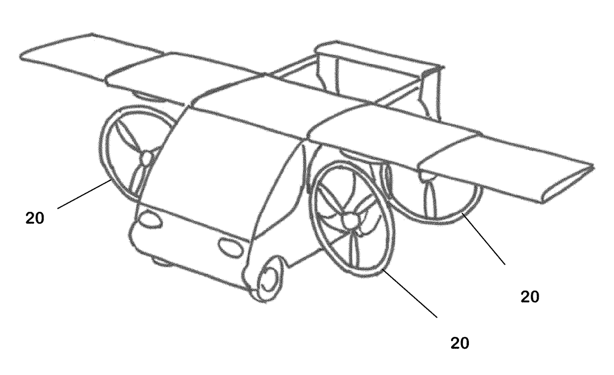
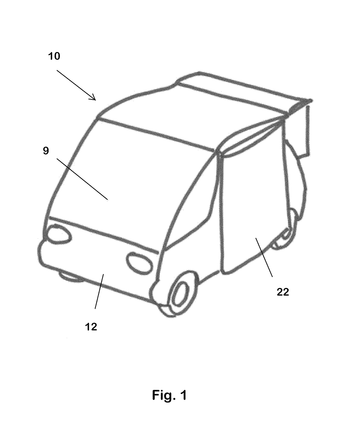
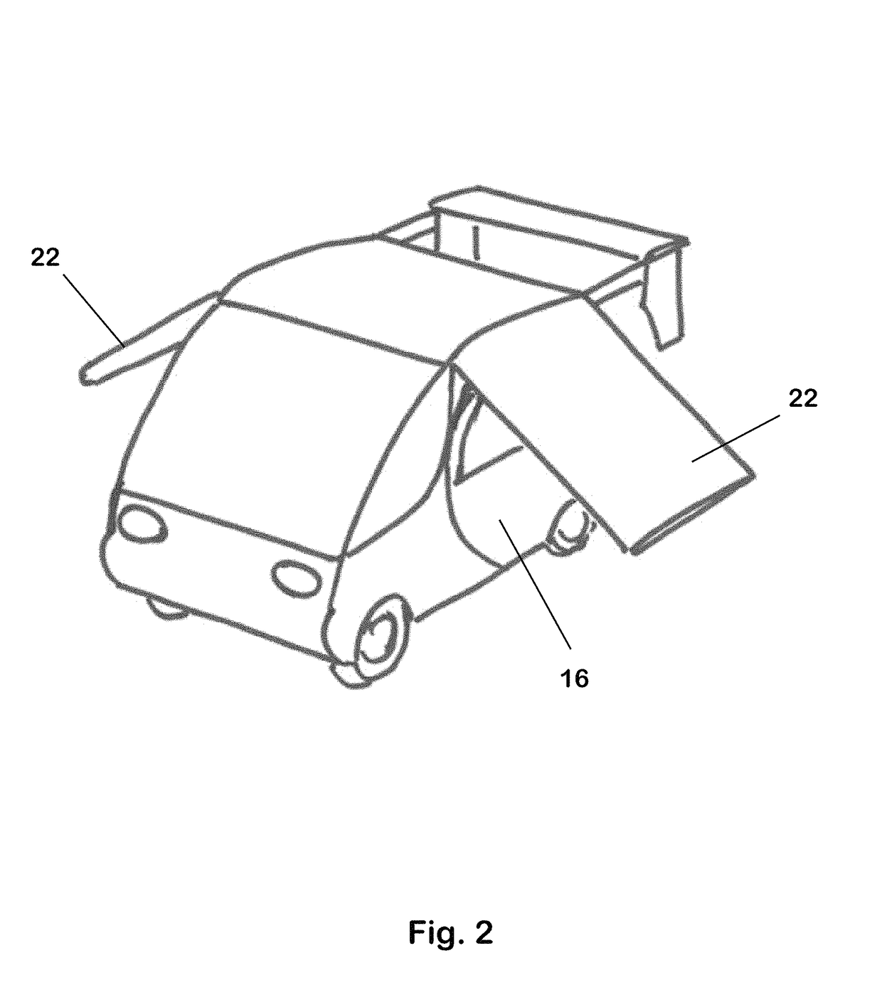
[0069]As shown in FIGS. 1 and 3, the vehicle comprises a main body 10 is in the shape of an automobile or an amphibious vehicle and which has a front end 12, a rear end 14 and side storage compartment cover doors 16 which close over storage compartments 18 formed in the sides of the vehicle. The compartments are sized to contain rotors / propellers 20 (hereafter “rotors”, FIG. 4), which can be folded into the compartments when not needed. The rotors can open and rotate independently.

[0070]A pair of foldable, extensible wings 22 (FIGS. 1-6), which are connected to the main body, also serve as covers for the storage compartments. Folding and extensible wings are well known in the art and therefore their constructional det...


PUM


Abstract

A vehicle which can travel on land, in water, or through air has a body like that of an automobile with powered wheels for providing propulsion on land. The vehicle also has rotors for providing propulsion in air and wings for providing lift. Storage compartments conceal the rotors during land operation, and in this mode the wings are folded down against the body, over the compartments. The wings and the rotors can be deployed to convert the vehicle to flight mode.

Description

[0001]This application claims benefit of provisional patent application No. 61 / 922,754, filed Dec. 31, 2013.[0002]This invention relates to a vehicle that has a roadable configuration similar to an automobile, wherein multiple rotors are stowed within the vehicle body, and a flying configuration in which the rotors are deployed, allowing the vehicle to take of and fly like a Vertical Take-Off and Landing (VTOL) / Short Take-off and Landing (STOL) aircraftBACKGROUND OF THE INVENTION[0003]Some aircraft are known, like the V22 Osprey, which have rotors that can tilt, allowing aircraft vertical take-off and landing.[0004]Helicopters' rotors can be tilted within certain limits, which is absolutely essential for their control. Yet, despite having the capability of six degrees of freedom for moving along or rotating around all three axes during flight configuration, helicopters on the ground usually have only very limited mobility, or none at all.[0005]Roadway used by land vehicles are becom...

Claims


Application Information

Patent Timeline
Patent Type & Authority Patents(United States)
IPC IPC(8): B64C37/02B64C37/00B64C29/00B60F5/02B60K6/20B64D25/00
CPCB64C37/00B60F5/02B60K6/20B64D25/00B64C29/0033Y10S903/903B60Y2200/92
Inventor RADU, BOGDAN
Owner RADU BOGDAN
Why Eureka
Try Eureka