Non-metallic vertebrae bend restrictor and vertebrae end piece
What is Al technical title?
Al technical title is built by PatSnap Al team. It summarizes the technical point description of the patent document.
a non-metallic, restrictor technology, applied in the direction of float cable installation, pipe laying and repair, mechanical equipment, etc., can solve the problems of high tensile bending load, internal pressure, hydrostatic load on the conduit,
Active Publication Date: 2018-10-16
MEARTHANE PRODS CORP
View PDF13 Cites 5 Cited by
Summary
Abstract
Description
Claims
Application Information
AI Technical Summary
This helps you quickly interpret patents by identifying the three key elements:
Problems solved by technology
Method used
Benefits of technology
Problems solved by technology
The flexible conduits are exposed to high tensile bending loads during installation and, once disposed in the water, are subjected to internal pressure, hydrostatic loading, high tensile loading and fatigue due to motion of the water or equipment, and loads caused directly or indirectly by unplanned activities.
Method used
Image
Click on the blue label to locate the original text in one second.
Reading with bidirectional positioning of images and text.
Examples
Embodiment Construction
[0014]One or more embodiments of the present invention are described in detail with reference to the accompanying figures. For consistency, like elements in the various figures are denoted by like reference numerals. In the following detailed description of the present invention, specific details are set forth in order to provide a thorough understanding of the present invention. In other instances, well-known features to one of ordinary skill in the art are not described to avoid obscuring the description of the present invention.
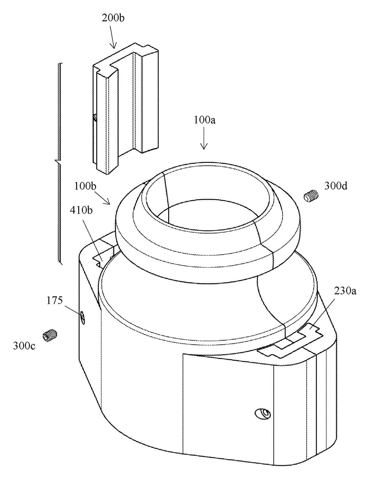
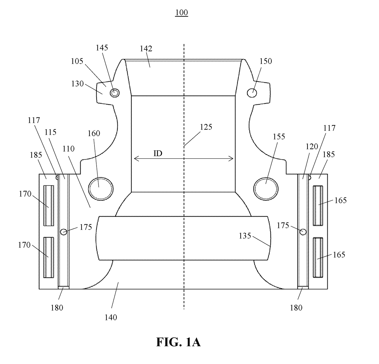
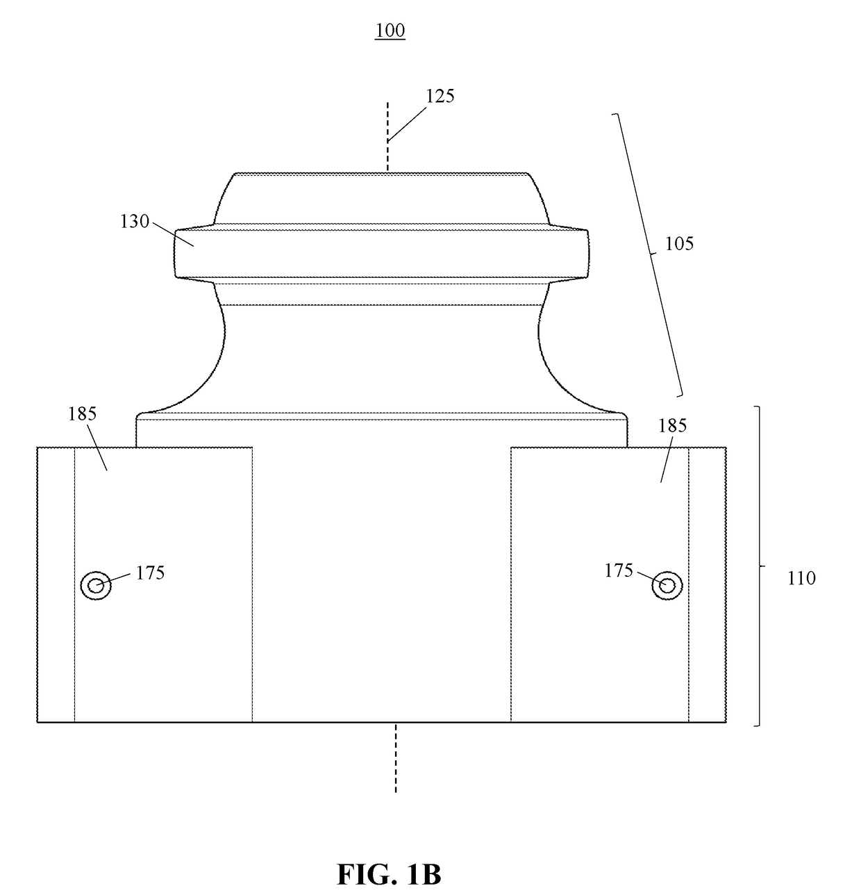
[0015]Conventional vertebrae bend restrictors are used in virtually all offshore drilling, production, and workover rigs as well as wind farms and are well known in the art. A conventional vertebrae bend restrictor includes a plurality of vertebrae, each comprised of a first member and a second member that connect around a portion of the conduit and are connected by metallic nuts and bolts typically comprised of steel, snap connections, straps, or zip ties...
PUM
Abstract
A non-metallic clip connection system includes a non-metallic clip having a substantially rectangular base portion, a first longitudinal flared wing portion, and a second longitudinal flared wing portion, wherein a plurality of edges of the clip along a path of insertion are beveled or radiused. The non-metallic clip connection system also includes a first non-metallic member having a first portion of a non-metallic clip receiver and a second non-metallic member having a second portion of the non-metallic clip receiver. The first non-metallic member is secured to the second non-metallic member by inserting the non-metallic clip in the non-metallic clip receiver. A non-metallic vertebrae bend restrictor and a non-metallic vertebrae end piece may use a non-metallic clip connection system.
Description
BACKGROUND OF THE INVENTION[0001]Conventional energy exploration, production, and workover uses one or more rigs, platforms, work vessels, or combinations thereof to perform drilling, completion, workover, or production operations. These operations may require one or more flexible flow lines, flying leads, mux lines, umbilicals, cables, or other flexible conduits. For example, in offshore applications, these flexible conduits may be used to connect certain surface-based equipment disposed on a platform above the waterline to subsea equipment in the water. These flexible conduits form the connective medium and may include one or more of electrical power and signal cabling, hydraulic power and activation cabling, chemical injection cabling, communications cabling, and robotic-operated vehicle cabling. The flexible conduits are exposed to high tensile bending loads during installation and, once disposed in the water, are subjected to internal pressure, hydrostatic loading, high tensile...
Claims
Application Information
Patent Timeline
Application Date:The date an application was filed.
Publication Date:The date a patent or application was officially published.
First Publication Date:The earliest publication date of a patent with the same application number.
Issue Date:Publication date of the patent grant document.
PCT Entry Date:The Entry date of PCT National Phase.
Estimated Expiry Date:The statutory expiry date of a patent right according to the Patent Law, and it is the longest term of protection that the patent right can achieve without the termination of the patent right due to other reasons(Term extension factor has been taken into account ).
Invalid Date:Actual expiry date is based on effective date or publication date of legal transaction data of invalid patent.