
Cervical traction collar

a cervical traction and collar technology, applied in the field can solve the problems of limiting or diminishing the therapeutic effect of cervical traction collars, limiting the mobility of users, and preventing users from working or being ambulatory

Active Publication Date: 2018-11-06
FREED WILLIAM L +1
View PDF4 Cites 0 Cited by
  • Summary
  • Abstract
  • Description
  • Claims
  • Application Information

AI Technical Summary

Benefits of technology

The present patent is about a cervical collar that can be used for cervical spinal traction without causing pressure on the jaw, chin, or temporomandibular joint. The collar is designed to provide pressure to the base of the skull at the occipital and / or mastoid region, which is the most effective area for treating cervical spine conditions. The collar is also comfortable and can be used in a sitting position. The technical effect of this invention is to provide a more effective and comfortable cervical traction device for treating cervical spine conditions.

Problems solved by technology

However, despite the wide use of such conventional cervical traction devices, these devices have several disadvantages that limit or diminish their therapeutic effect.
One disadvantage is that conventional cervical spine traction devices often limit the mobility of their users.
Many cervical spine traction devices require the user to lie down, thus prohibiting the user from working or being ambulatory.
Further, many cervical spine traction devices that require a user to lie down also tend to be highly expensive.
However, these conventional mobile cervical traction devices present their own disadvantages.
Conventional mobile cervical traction devices generate considerable pressure on the jaw, chin and temporomandibular joint of the patient.
The literature and evolution of clinical protocols indicates that sustained pressure to the jaw, chin and temporomandibular joint increases the likelihood of injury to the temporomandibular joint.
In addition to increasing the risk of injury to the patient, conventional mobile cervical spine traction devices are impractical for use for many work applications such as using a computer or sitting at a desk due to the upward pressure on the jaw and / or chin limiting user's field of view.
Due to the limitations discussed above, conventional cervical traction devices are not the best solutions for providing cervical spinal traction.

Method used


Image

  • Cervical traction collar
  • Cervical traction collar
  • Cervical traction collar

Examples


Embodiment Construction

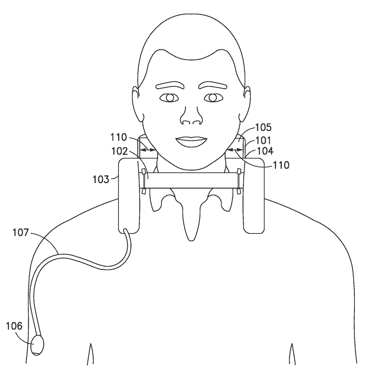
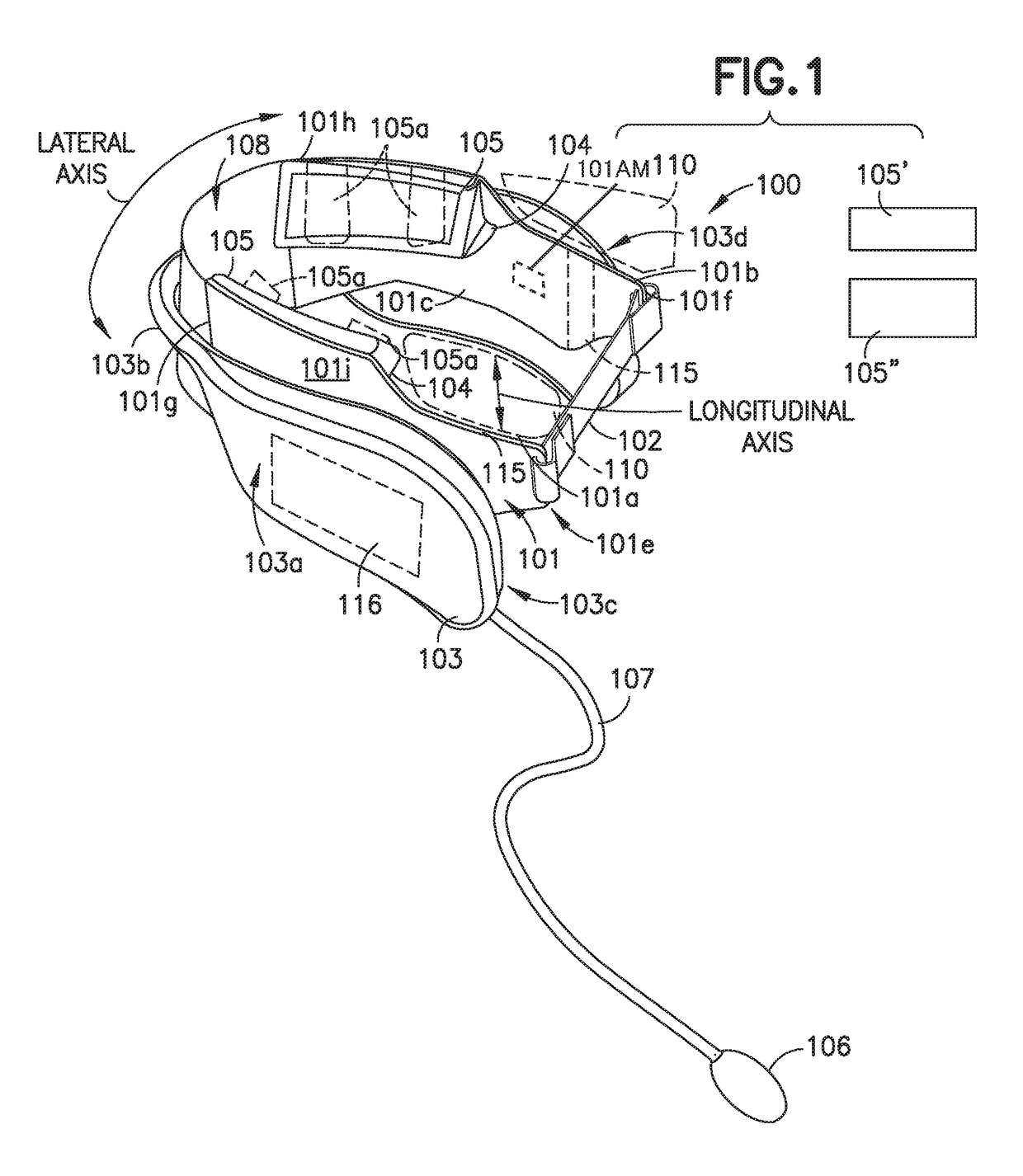
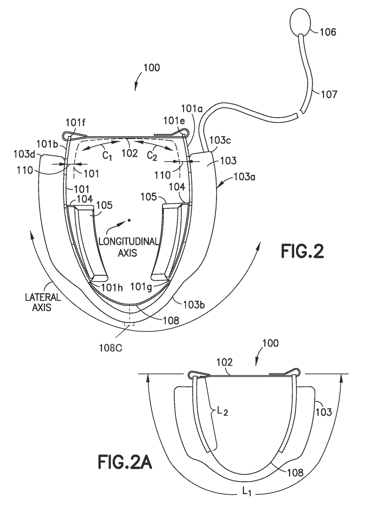
[0015]Referring now to FIGS. 1-2, a cervical collar 100 according to an aspect of the present disclosure is shown. The cervical collar 100 is a traction collar worn around the neck of a patient or wearer undergoing cervical spinal traction. The cervical collar 100 conforms substantially to the shape of the back of the wearer's neck and engages the shoulders of the wearer as well as the base of the wearer's skull at the occipital and / or mastoid region. The cervical collar 100 provides cervical traction pressure to the base of the skull at the occipital and / or mastoid regions without providing cervical traction pressure to the temporomandibular joint, jaw or chin of the wearer's skull. The cervical collar 100 provides the temporomandibular joint, jaw and / or chin with unobstructed clearance to enable unhindered movement. As illustrated in FIG. 1, the cervical collar 100 has a lateral axis that substantially runs along a length L1 of the cervical collar 100 (see FIG. 2A) as well as a lo...


PUM


Abstract

In accordance with one or more aspects of the disclosed embodiment, a cervical collar includes a semi-rigid collar substantially conforming to the back of a neck, an occipital locking mechanism coupled to the semi-rigid collar, configured to generally conform to and engage with the base of a skull at the occipital or mastoid region without engaging the temporomandibular joint, jaw or chin of the skull and a traction mechanism coupled to the semi-rigid collar, the at least one traction mechanism configured to provide cervical traction through the occipital locking mechanism of the semi-rigid collar against the base of the skull without pressure against the temporomandibular joint, jaw and chin.

Description

CROSS REFERENCE TO RELATED APPLICATIONS[0001]This application is a nonprovisional of and claims the benefit of U.S. Provisional Patent Application No. 61 / 897,282 filed Oct. 30, 2013, the disclosure of which is incorporated by reference herein in its entirety.BACKGROUND1. Field[0002]The present embodiment relates to a cervical traction collar, more particularly, to a cervical traction collar that exerts cervical traction pressure to the base of the skull without exerting pressure on the temporomandibular joint, the jaw and / or the chin.2. Brief Description of Related Developments[0003]Cervical spine traction has proven to be a valuable therapeutic tool for the treatment of many cervical spine conditions such as, for example, discogenic and spondylogenic neck and arm pain. The method has also been successfully employed to help treat muscle spasms, relieve pressure on nerves and help the alignment of cervical neck bones. Because of the effectiveness of cervical spine traction as a conva...

Claims


Application Information

Patent Timeline
Patent Type & Authority Patents(United States)
IPC IPC(8): A61F5/055A61F5/01
CPCA61F5/012A61F5/055A61F2250/0003
Inventor FREED, WILLIAM L.FREED, MATTHEW W.
Owner FREED WILLIAM L
Learn More