
System and method of correcting banding artifacts in cardiac CT

a banding artifact and cardiac ct technology, applied in the field of diagnostic imaging, can solve the problems of increasing vessel visualization and reporting difficulty, and affecting the accuracy of ct images

Active Publication Date: 2018-11-20
GENERAL ELECTRIC CO
View PDF20 Cites 1 Cited by
  • Summary
  • Abstract
  • Description
  • Claims
  • Application Information

AI Technical Summary

Benefits of technology

The patent describes a way to make images clearer and more accurate in a CT system. It does this by reducing the mis-registration of vessels and improving the separation of greyscale levels between slabs.

Problems solved by technology

However, many systems (new or legacy) typically do not include a detector that has an axial length that is greater than that of the heart.
Since the introduction of Cardiac CT imaging, the presence of banding artifacts has been one of the limitations of the technology.
They can affect all structures in the images, but are most problematic on coronaries as they can show an artificial “rupture” in the vessel.
Although the diagnostic remains most the times possible by looking at both “sides” of the vessel individually, the artifacts often create complaints from the customers as it makes vessel visualization and reporting more difficult.
However, for a variety of reasons, various types of imaging artifacts can occur.

Method used


Image

  • System and method of correcting banding artifacts in cardiac CT
  • System and method of correcting banding artifacts in cardiac CT
  • System and method of correcting banding artifacts in cardiac CT

Examples


Embodiment Construction

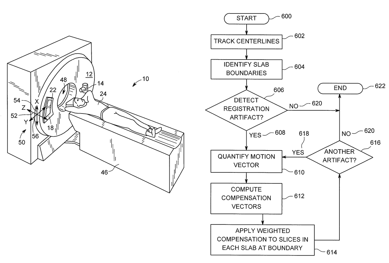
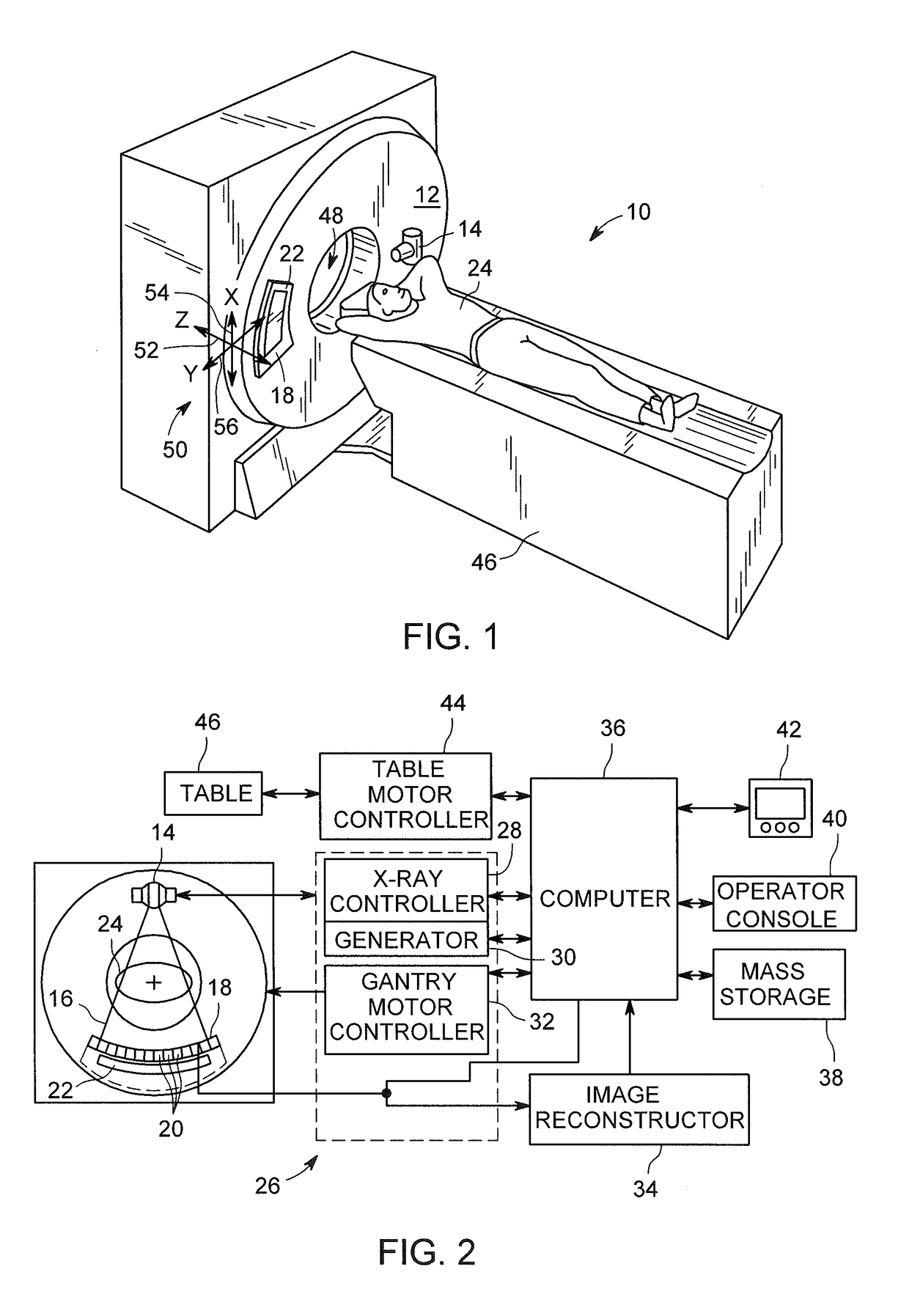
[0029]Disclosed is a post-processing approach which reduces cardiac CT banding artifacts by focusing on the coronary arteries. The disclosed process provides a dedicated post-processing filter that the user can switch ON or OFF to compensate for the banding artifacts on a given vessel. The filter will leverage the centerline used to visualize the vessel to detect potential slab-to-slab misalignments artifact, quantify it, and eventually compensate for it with vessel-centered local deformation. Additionally / subsequently, the “seam artifact” that can occur at a slab-to-slab boundary is minimized with an adaptive greyscale de-banding technique that preserves the integrity of the vessel, avoiding the possibility of creating new artifacts within / near the vessel due to the greyscale debanding correction itself (that could be misinterpreted as a pathology).

[0030]The operating environment of disclosed embodiments is described with respect to a sixty-four-slice computed tomography (CT) syste...


PUM


Abstract

A CT system includes a gantry having a rotatable base and having an opening for receiving an object to be scanned, an x-ray source, a CT detector, and a computer programmed to detect a mis-registration at a slab boundary between a first slab and a second slab of a reconstructed image, quantify an amount of mis-registration at the slab boundary, and adjust the reconstructed image at the slab boundary based on the quantification.

Description

CROSS-REFERENCE TO RELATED APPLICATION[0001]The present application claims priority to U.S. Provisional Application 61 / 833,227 filed Jun. 10, 2013, the disclosure of which is incorporated herein in its entirety.BACKGROUND[0002]This disclosure relates generally to diagnostic imaging and, more particularly, to an improved method of post processing reconstructed CT images to improve vessel mis-registration and greyscale de-banding between slabs within a CT image.[0003]Typically, in computed tomography (CT) imaging systems, an x-ray source emits a fan or cone-shaped beam toward a subject or object, such as a patient or a piece of luggage. Hereinafter, the terms “subject” and “object” shall include anything capable of being imaged. The beam, after being attenuated by the subject, impinges upon an array of radiation detectors. The intensity of the attenuated beam radiation received at the detector array is typically dependent upon the attenuation of the x-ray beam by the subject. Each det...

Claims


Application Information

Patent Timeline
Patent Type & Authority Patents(United States)
IPC IPC(8): A61B6/03G06K9/78A61B6/00G06K9/46G06K9/62G06K9/20G06K9/56G06T3/00G06T5/50G06T7/00G06T11/00A61B6/04G06T5/00
CPCA61B6/5241A61B6/5235A61B6/5258A61B6/504A61B6/5288G06K9/4638G06K9/6204G06T3/0068G06T2211/404G06K9/78G06K2009/2045G06T5/002G06T7/0016G06T11/008G06T2207/10081G06T2207/20221G06T2207/20228G06T2207/30048G06T2207/30101G06T2207/30112A61B6/032A61B6/0457A61B6/486A61B6/503A61B6/5264G06K9/56G06K9/6202G06K9/6203G06T2211/412A61B6/0487G06T5/70G06T3/14
Inventor LAUNAY, LAURENTOKERLUND, DARIN R.RUIZ, GUILLERMONETT, BRIAN E.
Owner GENERAL ELECTRIC CO
Learn More