
Electronic element support frame, electronic element assembly, and electrical assembly

a technology for electronic elements and support frames, which is applied in the direction of electrical apparatus construction details, instruments, heat measurement, etc., can solve the problems of loss of electronic element functions and pin contact errors, and achieve the effects of enhancing safety and stability of electronic elements, avoiding erroneous contact, and enhancing electric insulation performance and voltage resistance performan

Active Publication Date: 2018-11-20
TYCO ELECTRONICS (SHANGHAI) CO LTD +1
View PDF4 Cites 0 Cited by
  • Summary
  • Abstract
  • Description
  • Claims
  • Application Information

AI Technical Summary

Benefits of technology

[0003]One of the objectives of the present disclosure is to provide an electronic element support frame, electronic element subassembly, and electrical subassembly, which avoids erroneous contact between pins, to thereby overcome the drawbacks of the prior art.
[0013]Compared with the prior art, the electronic element support frame according to the present disclosure accommodates the pins through a pair of accommodating parts, respectively, which avoids erroneous contact between the two pins. The isolative wall may enhance the electric insulation performance and the voltage-withstanding performance between the two pins and further enhance safety and stability of the electronic element. The electronic element support frame has a simplified manufacturing process and is easy to be assembled with the electronic element without additional protection processing to the pins and additional protection part, thereby reducing the manufacturing cost while enhancing the safe and stable performance.

Problems solved by technology

Erroneous contact of the pair of pins will cause loss of the functions of the electronic element.
The pins are generally made of a relatively flexible material such that their extension paths easily change, which will very easily cause the erroneous contact of the pins.
How to guarantee that the pins will not contact erroneously is an issue to address.

Method used


Image

  • Electronic element support frame, electronic element assembly, and electrical assembly
  • Electronic element support frame, electronic element assembly, and electrical assembly
  • Electronic element support frame, electronic element assembly, and electrical assembly

Examples


embodiment 1

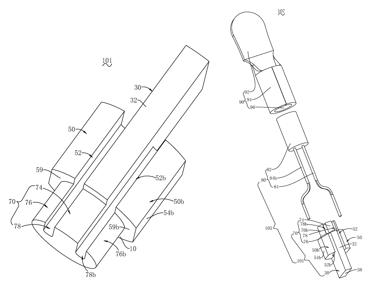
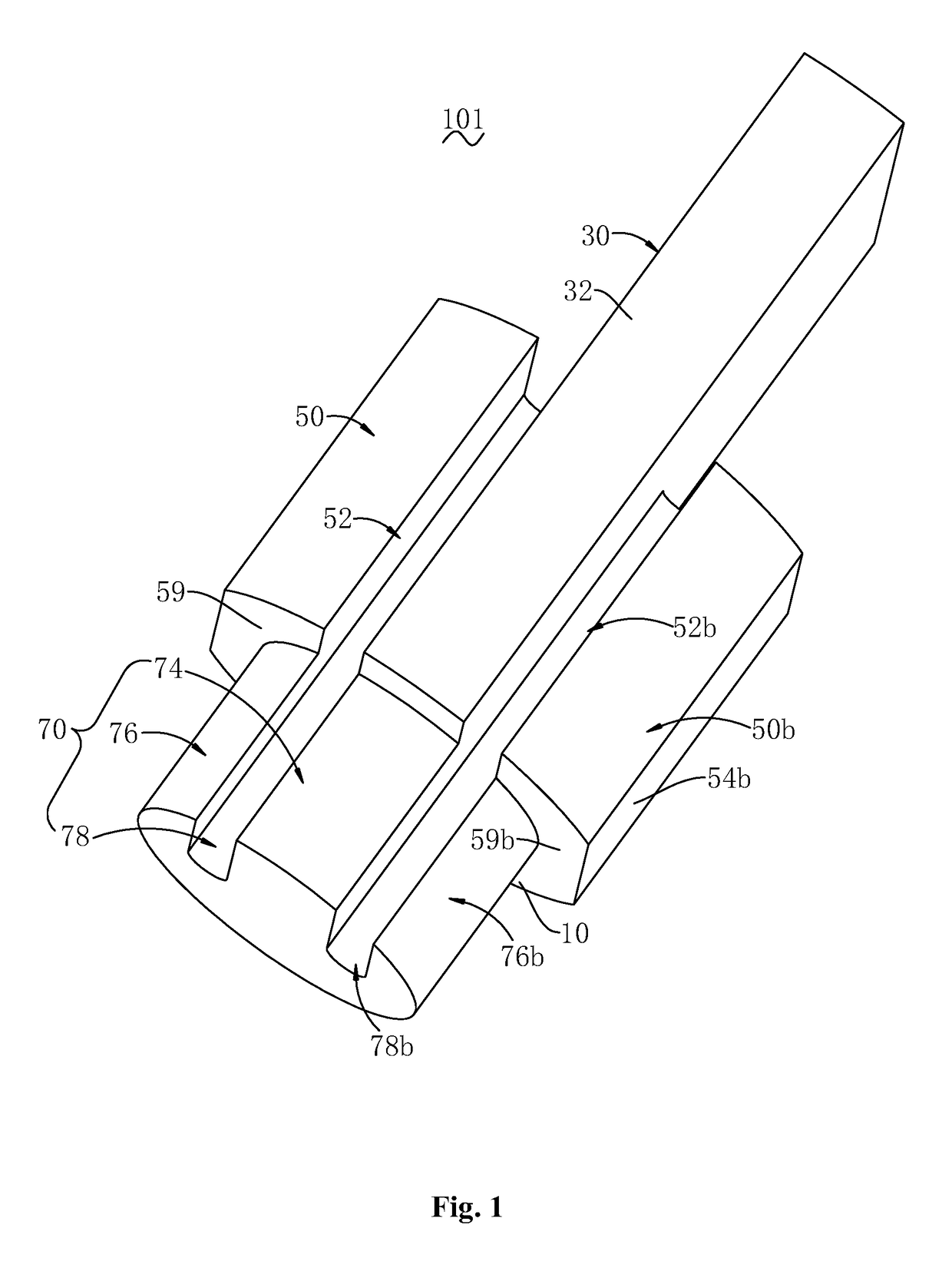
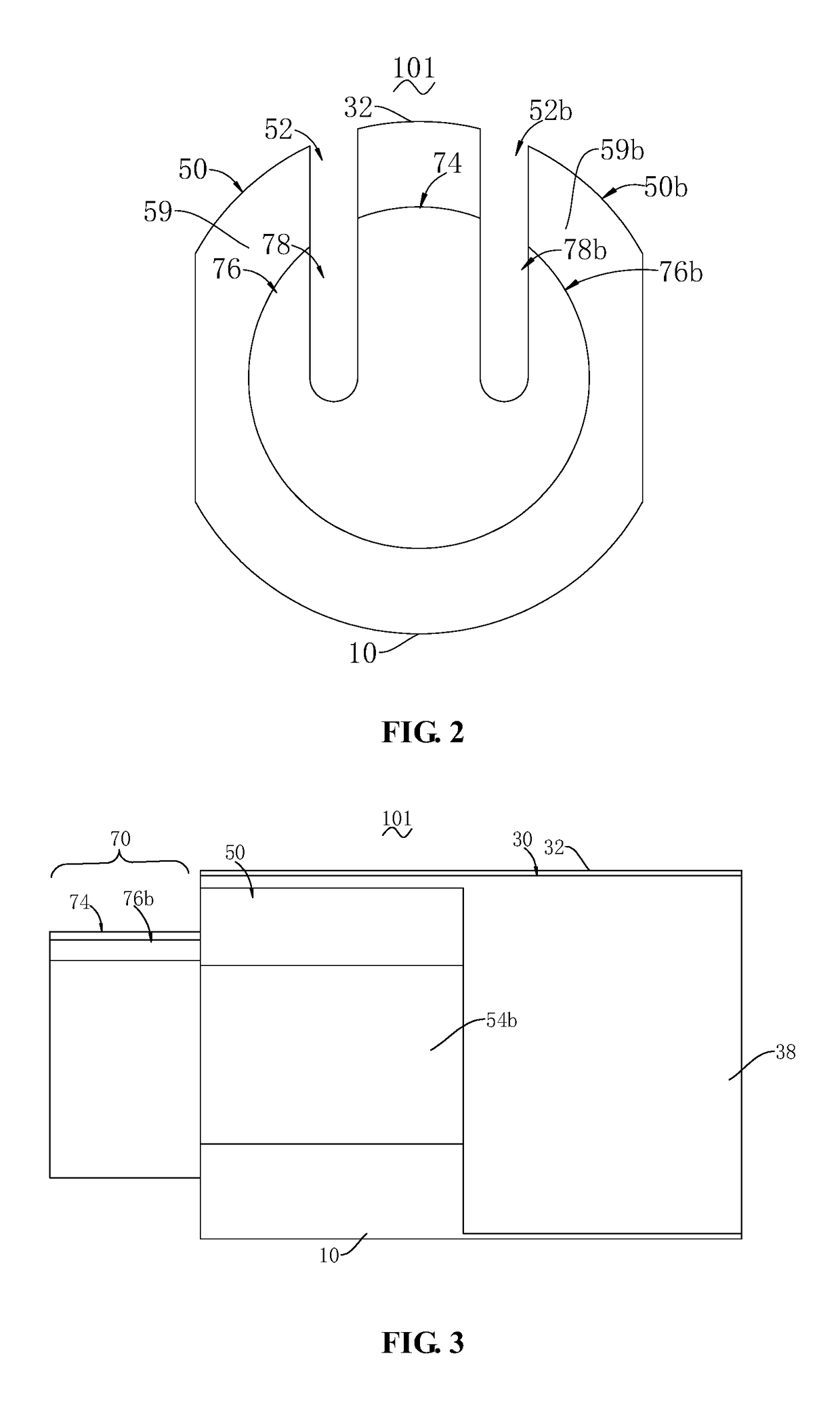
[0036]With reference to FIGS. 1-10, the present disclosure provides an electronic element support frame 101. The electronic element support frame 101 comprises an isolative wall 30 and a pair of retaining parts 50, 50b. The pair of retaining parts 50, 50b are arranged at two sidewalls of the isolative wall 30, respectively, and together with the sidewalls of the isolative wall 30 enclose a pair of accommodating parts 52, 52b.

[0037]The electronic element support frame 101 comprises a body 10. The body 10 is arranged for supporting the isolative wall 30 and the pair of retaining parts 50, 50b. The body 10 is arranged to extend along an axial direction of the electronic element support frame 101. In other words, the body 10 has an axial direction. The specific structure and shape of the body 10 are only required to meet corresponding support requirements. In this embodiment, to facilitate being mounted to other components, a bottom face of the body 10 is substantially a partial cylind...

embodiment 2

[0048]With reference to FIGS. 11-14, as a variation to Embodiment 1, the present disclosure provides another electronic element support frame 101b. Different from Embodiment 1, a pair of retaining parts 50, 50b of the electronic element support frame 101b are provided with through-holes 55, 55b. The through-holes 55, 55b are arranged for retaining the pins 84, 84b. During mounting, the pins 84, 84b may be directly inserted into the through-holes 55, 55b. The electronic element support frame 101b may be integrally column-shaped.

embodiment 3

[0049]With reference to FIGS. 15-20, as another variation to Embodiment 1, the present disclosure provides yet another electronic element support frame 101c. Different from Embodiment 1, the electronic element support frame 101c comprises retaining parts 56, 56b and mating retaining parts 58, 58b that may be disposed opposite to each other.

[0050]Specifically, the retaining parts 56, 56b are provided with accommodating parts 52c, 52d. The accommodating parts 52c, 52d are transversely arranged apart along the isolative wall 30. The accommodating parts 52c, 52d are arranged to retain the corresponding pins 84, 84b. The accommodating parts 52c, 52d are arranged to axially extend along the insulative wall 30. In this embodiment, the accommodating parts 52c, 52d are bottom portion grooves. The accommodating parts 52c, 52d may be axially through-grooves.

[0051]The mating retaining parts 58, 58b are arranged to up-down abut against the retaining parts 56, 56b. The mating retaining parts 58, ...


PUM


Abstract

The present disclosure discloses an electronic element support frame, an electronic element assembly, and an electrical assembly. The electronic element support frame has a body, an isolative wall, and a pair of retaining parts. The body has an axial direction. The isolative wall is arranged to continuously extend along the axial direction of the body. The pair of retaining parts are arranged on the body and disposed at two sides of the isolative wall, respectively. The retaining parts together with the isolative wall enclose a pair of accommodating parts, respectively. The accommodating parts extend continuously along the axial direction of the isolative wall to accommodate pins of the electronic element, respectively. The electronic element support frame of the present disclosure can avoid erroneous contact between the pins of the electronic element, thereby enhancing safety performance.

Description

FIELD OF THE INVENTION[0001]The present disclosure relates to a structure for supporting an electronic element, and more particularly to an electronic element support frame, electronic element assembly, and electrical assembly.BACKGROUND OF THE INVENTION[0002]An electronic element is useful for implementing a specific electric function. To implement corresponding electric transmission, the electronic element is generally electrically connected to other devices via pins, thereby implementing transmission of electrical signals. To meet requirements for input / output or connection to positive and negative poles, the electronic element generally requires a pair of pins. Erroneous contact of the pair of pins will cause loss of the functions of the electronic element. The pins are generally made of a relatively flexible material such that their extension paths easily change, which will very easily cause the erroneous contact of the pins. How to guarantee that the pins will not contact erro...

Claims


Application Information

Patent Timeline
Patent Type & Authority Patents(United States)
IPC IPC(8): H02B1/01H05K7/10
CPCH05K7/1084G01K1/14
Inventor WANG, JIFAZHOU, XIAOZHAO, CANCANYIN, HAOMAI
Owner TYCO ELECTRONICS (SHANGHAI) CO LTD
Learn More