Card connector

A card connector and card body technology, applied in the direction of connection, preventing wrong connection devices, contact parts, etc., can solve problems such as poor contact, short circuit, deformation of elastic contact pieces, etc. short circuit effect

Inactive Publication Date: 2014-08-13
SMK CO LTD
View PDF4 Cites 1 Cited by
  • Summary
  • Abstract
  • Description
  • Claims
  • Application Information

AI Technical Summary

Problems solved by technology

[0013] However, in the prior art as described above, if the movement of the movable end in the floating direction is not restricted, the movable end of the elastic contact piece may float excessively when the card body is inserted. , or an impact is applied due to dropping, etc., causing deformation of the elastic contact piece portion, in which case, when using Figure 10 In the case of a card as shown, the contacts are in contact with a signal transmission terminal other than the signal transmission terminal that should be in contact, and a short circuit may be caused by the wrong contact.
[0014] On the other hand, as in the conventional example shown in Patent Document 2, a shoulder protruding from the movable end is integrally provided on the bottom plate made of an insulating synthetic resin material, and the shoulder protrudes from the movable end in the floating direction of the movable end. When the movement of the elastic contact piece is restricted, the movable end made of the sheet metal slides between the slidable part and the shoulder along with the elastic deformation of the elastic contact piece. Therefore, at the edge of the sliding movable end, the The inner surface of the sliding part or the shoulder made of insulating synthetic resin is cut, and the cut resin material may prevent the contacts from contacting the signal transmission terminal, and the movable end is hooked on the bottom of the insertion groove. Or the cut part of the shoulder may cause failure in the prescribed movement of the elastic contact piece, which may cause unexpected deformation or poor contact of the elastic contact piece.

Method used


Image

  • Card connector
  • Card connector
  • Card connector

Examples


Embodiment Construction

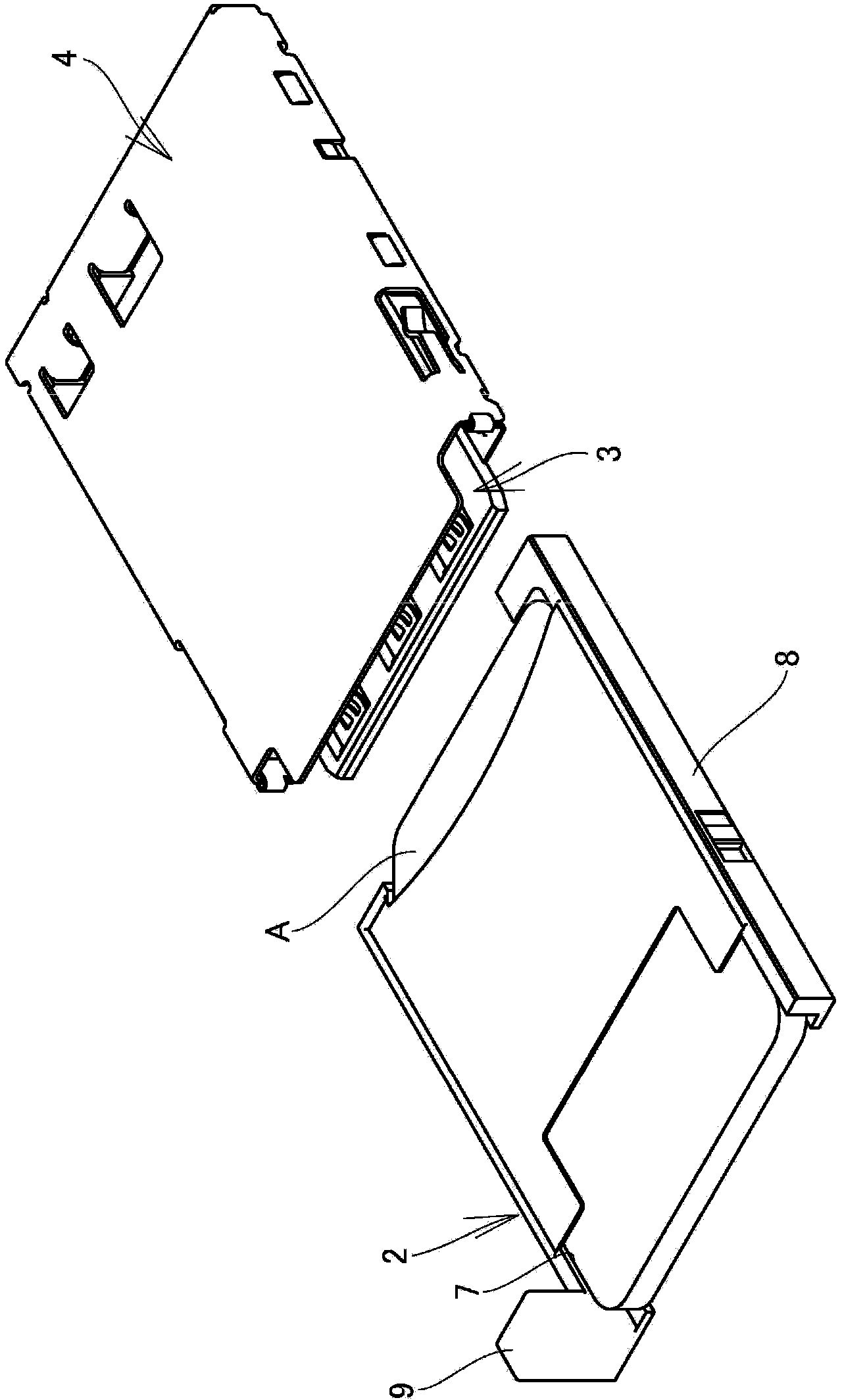
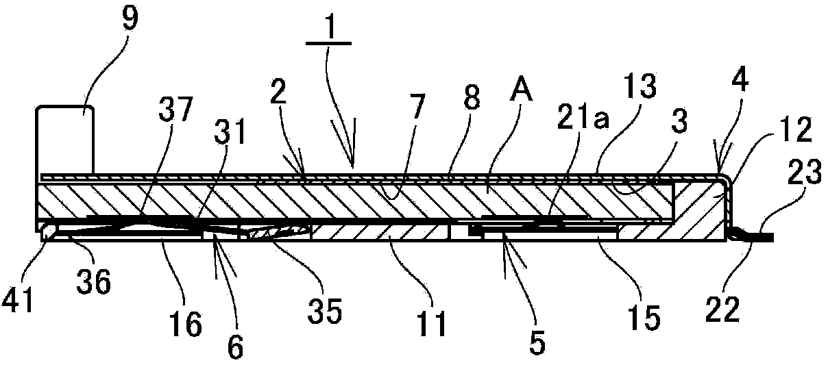
[0041] Next, according to Figure 1 to Figure 9 The illustrated embodiment illustrates an implementation of the card connector of the present invention. In addition, symbol 1 is a card connector. In addition, the same code|symbol is attached|subjected and demonstrated to the structure similar to the said conventional example, and the code|symbol A in a drawing is a card, such as an IC card.

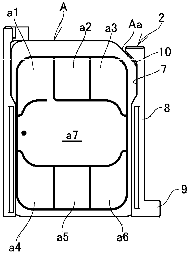
[0042] The card connector 1 has a housing 4 having a card insertion portion 3 into which a card body 2 is inserted, and a plurality of contacts 5 made of a conductive metal material that are supported on the housing 4 and protrude from the inner bottom of the card insertion portion 3. , 5..., 6, 6..., by contacting the signal transmission terminals a1-a6 on one side of the card body 2 inserted into the card insertion part 3 with the corresponding contacts, thereby electrically connecting the card A through the card connector 1 with the connection substrate.

[0043] Such as image 3 A...


PUM


Abstract

The invention provides a card connector which can prevent accidental deformation of a contact when a card body is plugged and can prevent short circuit caused by mistaken contact of the contact. The card connector (1) is provided with an outer shell (4) and a plurality of contacts, wherein the outer shell is provided with a card plug part (3) where the card body (2) can be plugged, the card plug part is formed on a base plate part (!1) formed by an insulating synthesized resin, the contacts contact with signal transmission terminals that are exposed at one face of the card body (2), a contact (6) is provided with an elastic contact sheet part (31), one end of the elastic contact sheet part (31) is a support end part (36) used for supporting the base plate part, the other end is a movable end part (34) that can move relative to the base plate part (11), the movable end part (34) is provided with an insulating cover body (35) formed by an insulating part, and the insulating cover body (35) is placed between the movable end part (94) and the card body (2).

Description

technical field [0001] The present invention relates to a card connector for connecting cards such as IC cards and flash memory cards to electronic devices such as mobile phones and smart phones. Background technique [0002] Conventionally, a card such as an IC card provided with a plurality of signal transmission terminals on one side has been used as an external storage medium of electronic equipment such as a mobile phone or a smartphone, and the card is electrically connected to a printed circuit board mounted on the electronic equipment through a card connector. [0003] Cards used as external storage media, such as using Figure 10 In the card with the structure shown, a plurality of signal transmission terminals (pads) a1 to a6 are formed by separating the conductive metal thin plate material into a mutually insulated state, and one of the signal transmission terminals a1 and the conductive metal The state where the central portion a7 of the sheet material is turned ...

Claims


Application Information

Patent Timeline
Patent Type & Authority Applications(China)
IPC IPC(8): H01R13/24H01R13/64H01R12/71
Inventor 镰谷裕康
Owner SMK CO LTD
Why Eureka
Try Eureka