Generating UV maps for modified meshes

a technology of 3d meshes and uv panels, applied in the direction of 2d-image generation, instruments, texturing/coloring, etc., can solve the problems of not maintaining the same relationship and the textures mapped to the changed 3d geometry via the uv panels

Active Publication Date: 2019-01-29
PIXAR ANIMATION
View PDF10 Cites 2 Cited by
  • Summary
  • Abstract
  • Description
  • Claims
  • Application Information

AI Technical Summary

Problems solved by technology

This can cause textures mapped to the changed 3D geometry via the UV panels to not look correct, or to not maintain the same relationship with the underlying 3D geometry as before the geometry was changed.

Method used


Image

  • Generating UV maps for modified meshes
  • Generating UV maps for modified meshes
  • Generating UV maps for modified meshes

Examples


Embodiment Construction

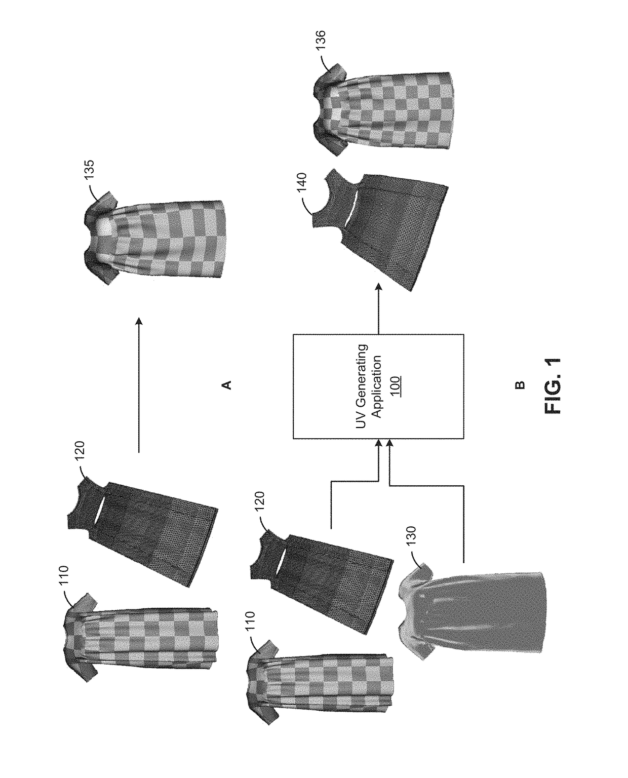
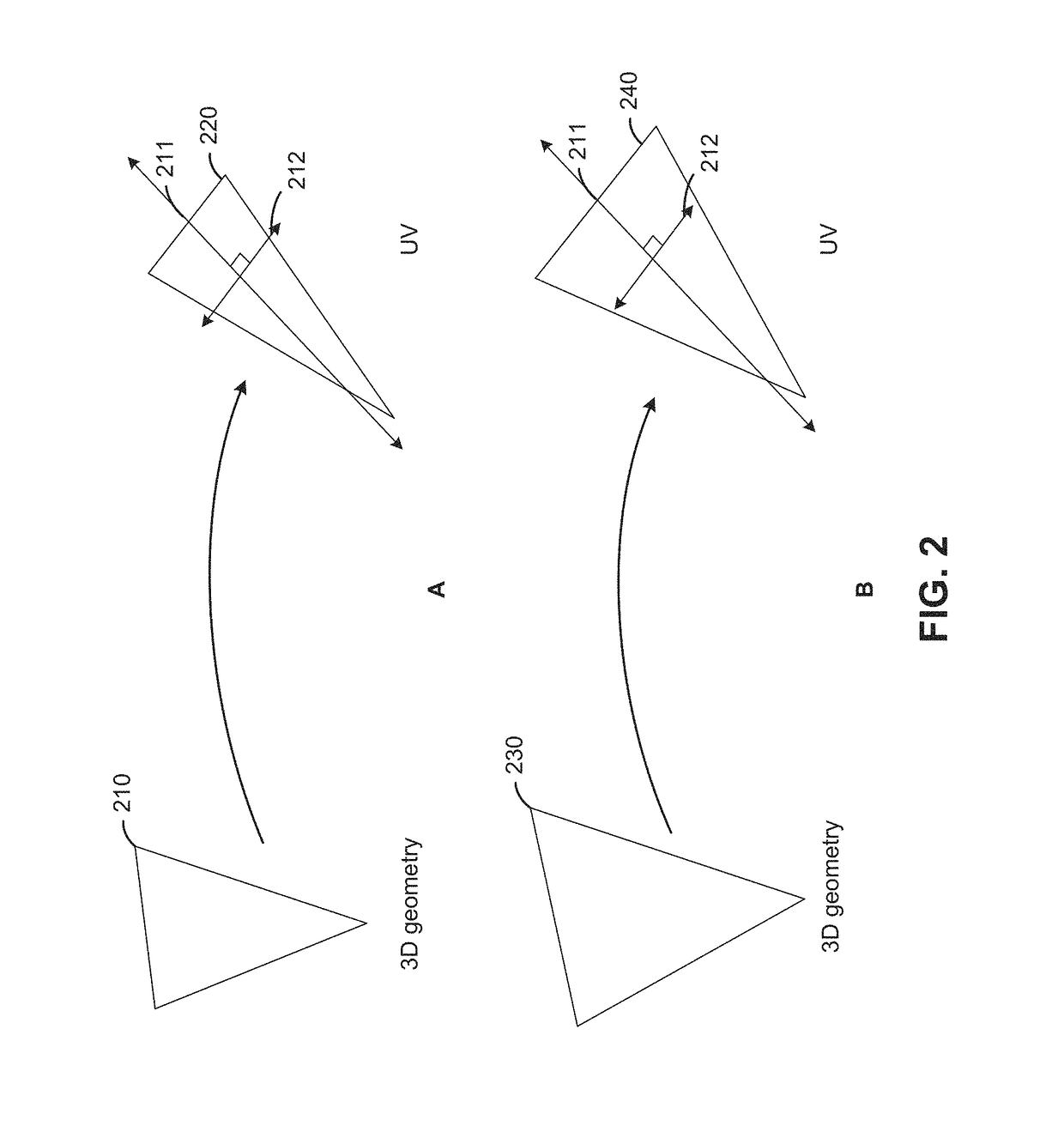
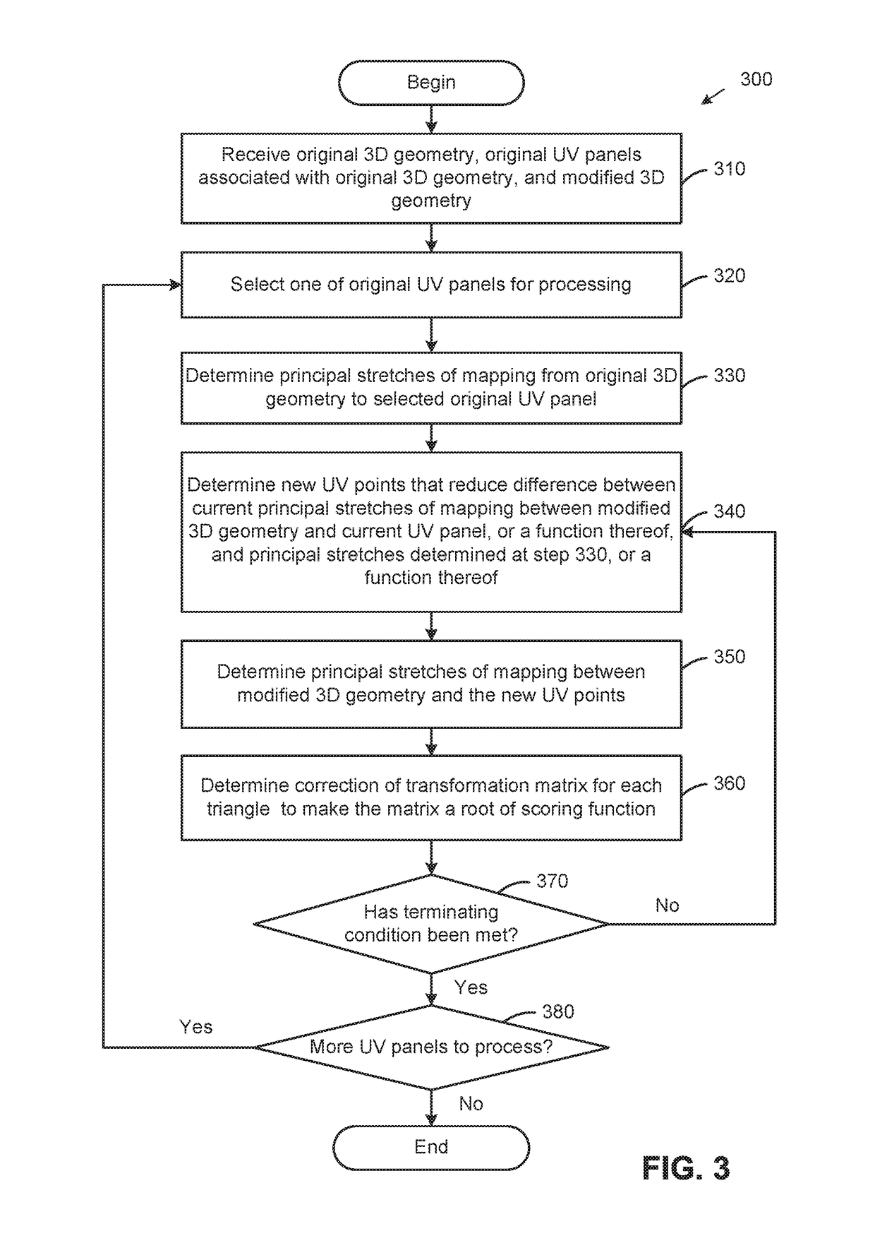
[0012]Embodiments disclosed herein provide techniques for automatically generating UV maps for modified three-dimensional (3D) virtual geometry. In one embodiment, a UV generating application may receive original 3D geometry and associated UV panel(s), as well as modified 3D geometry created by deforming the original 3D geometry. To generate UV panel(s) for the modified 3D geometry, the UV generating application first extracts principal stretches of a mapping between the original 3D geometry and the associated UV panel(s), and the UV generating application then transfers the principal stretches, or a function thereof, to a mapping from the modified 3D geometry to new UV panel(s). As used herein, “principal stretches” generally refer to the longest and shortest stretches in transforming a triangle in a 3D geometry to a corresponding triangle in a UV panel, similar to the principal axes of an ellipse. In one embodiment, transferring the principal stretches or a function thereof may in...


PUM


Abstract

This disclosure provides an approach for automatically generating UV maps for modified three-dimensional (3D) virtual geometry. In one embodiment, a UV generating application may receive original 3D geometry and associated UV panels, as well as modified 3D geometry created by deforming the original 3D geometry. The UV generating application then extracts principal stretches of a mapping between the original 3D geometry and the associated UV panels and transfers the principal stretches, or a function thereof, to a new UV mapping for the modified 3D geometry. Transferring the principal stretches or the function thereof may include iteratively performing the following steps: determining new UV points assuming a fixed affine transformation, determining principal stretches of a transformation between the modified 3D geometry and the determined UV points, and determining a correction of a transformation matrix for each triangle to make the matrix a root of a scoring function.

Description

BACKGROUNDField of the Invention[0001]Aspects of the disclosure presented herein relate to rendering of three-dimensional virtual geometry. More specifically, this disclosure presents techniques for automatically generating UV maps for modified 3D meshes.Description of the Related Art[0002]UV mapping is an approach for mapping two-dimensional (2D) textures to three-dimensional (3D) geometry. The letters “U” and “V” in UV mapping denote axes of the 2D texture, as opposed to the X, Y, Z coordinates of the 3D geometry. Artists will often meticulously place UVs in relation to 3D geometry they create by flattening the 3D geometry into one or more corresponding 2D UV panels. However, when the 3D geometry is changed, such as through deformation, the existing UV panels are typically just copied and pasted onto the changed 3D geometry. This can cause textures mapped to the changed 3D geometry via the UV panels to not look correct, or to not maintain the same relationship with the underlying ...

Claims


Application Information

Patent Timeline
Patent Type & Authority Patents(United States)
IPC IPC(8): G06T15/00G06T11/00G06T17/20G06T19/20G06T15/04
CPCG06T15/04G06T19/20G06T17/205G06T11/001
Inventor DE GOES, FERNANDO FERRARIMEYER, MARK
Owner PIXAR ANIMATION
Why Eureka
Try Eureka