UV mapping method based on rasterization rendering and cloud equipment

A mapping method and rasterization technology, applied in the computer field, can solve the problems of time-consuming cost and labor cost, and achieve the effect of reducing the amount of calculation

Pending Publication Date: 2021-12-03
广州引力波信息科技有限公司
View PDF0 Cites 0 Cited by
  • Summary
  • Abstract
  • Description
  • Claims
  • Application Information

AI Technical Summary

Problems solved by technology

From the production-acceptance-modification p

Method used


Image

  • UV mapping method based on rasterization rendering and cloud equipment
  • UV mapping method based on rasterization rendering and cloud equipment
  • UV mapping method based on rasterization rendering and cloud equipment

Examples


Embodiment Construction

[0024] In order to have a clearer understanding of the above purpose, features and advantages of the present application, the present application will be further described in detail below in conjunction with the accompanying drawings and specific embodiments. It should be noted that, in the case of no conflict, the embodiments of the present application and the features in the embodiments can be combined with each other.

[0025] In the following description, many specific details are set forth in order to fully understand the application, but the application can also be implemented in other ways different from those described here, therefore, the protection scope of the application is not limited by the specific details disclosed below. EXAMPLE LIMITATIONS.

[0026]Some embodiments of the present application are described below with reference to the accompanying drawings.

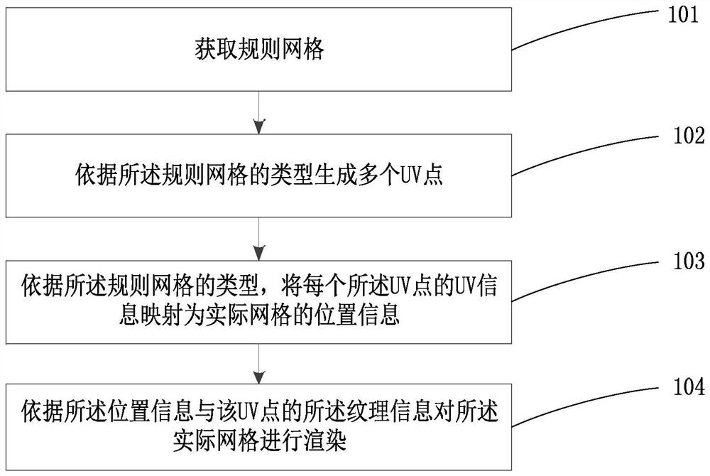
[0027] Such as figure 1 As shown, the present application provides a UV mapping method based on raste...


PUM


Abstract

The invention belongs to the technical field of computers, and particularly relates to a UV mapping method based on rasterization rendering and cloud equipment. The method comprises the steps of: obtaining a regular grid; generating a plurality of UV points according to the type of the regular grid, each UV point comprising UV information and texture information; mapping the UV information of each UV point into position information of an actual grid according to the type of the regular grid; and rendering the actual grid according to the position information and the texture information of the UV points. The method has the advantages that compared with a traditional mapping method, the calculation amount of the UV mapping method can be reduced, computer resources can be fully utilized by accelerated operation of the method through a GPU, and the effect of modifying and adjusting the UV points in real time is achieved. The invention further provides cloud equipment to execute the UV mapping method based on rasterization rendering, so that the effect of rendering the actual grid by using the texture information of the regular grid is achieved.

Description

technical field [0001] The present application belongs to the field of computer technology, and in particular relates to a UV mapping method based on rasterization rendering and a cloud device. Background technique [0002] The traditional texture UV mapping operation is implemented by ray tracing. Based on the idea of ​​recursion and search, the light hits a surface point of the actual grid, and the vertex of the intermediate grid surface is found according to the information pointed to by this point, and then UV is generated. information. [0003] Under this traditional texture UV operation, the user needs to edit the UV information of the vertices of the model mesh from the 3D art in the offline software, and then hand it over to the 3D art engineer for delivery. If there is any problem, it needs to be called back for re-editing. The process from production-acceptance-modification requires considerable time and labor costs. [0004] With the increasing business volume o...

Claims


Application Information

Patent Timeline
IPC IPC(8): G06T15/04G06T15/50
CPCG06T15/04G06T15/50
Inventor 赵俊杰陈健豪
Owner 广州引力波信息科技有限公司
Why Eureka
Try Eureka