

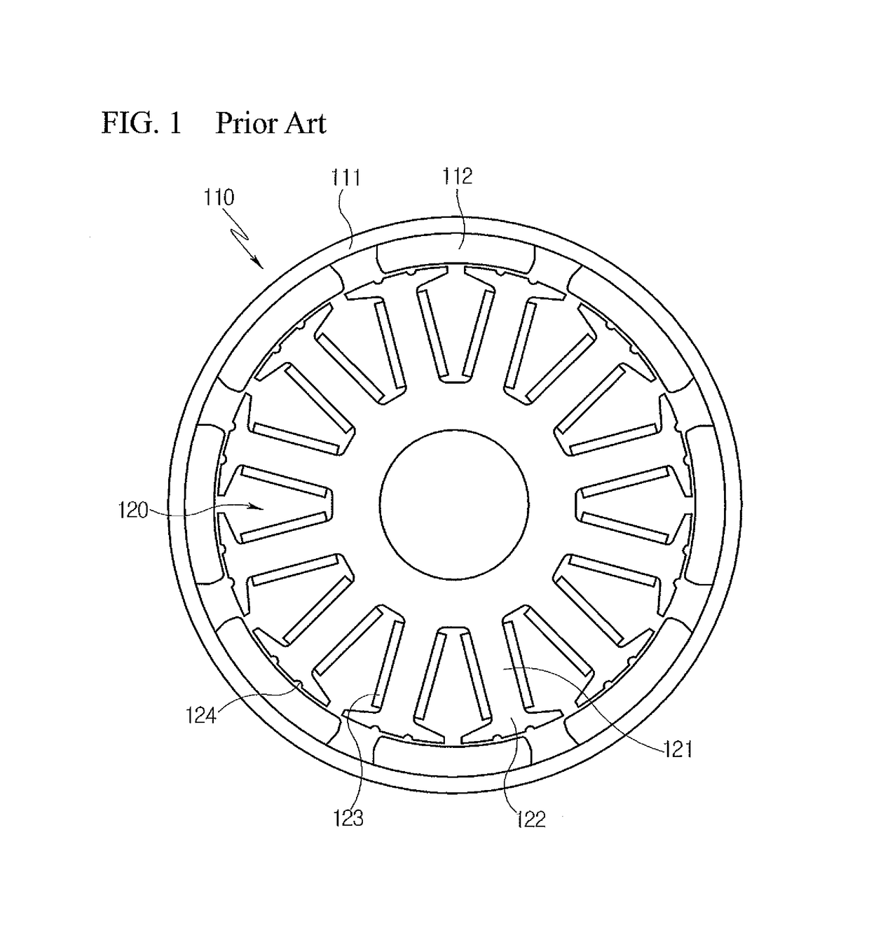
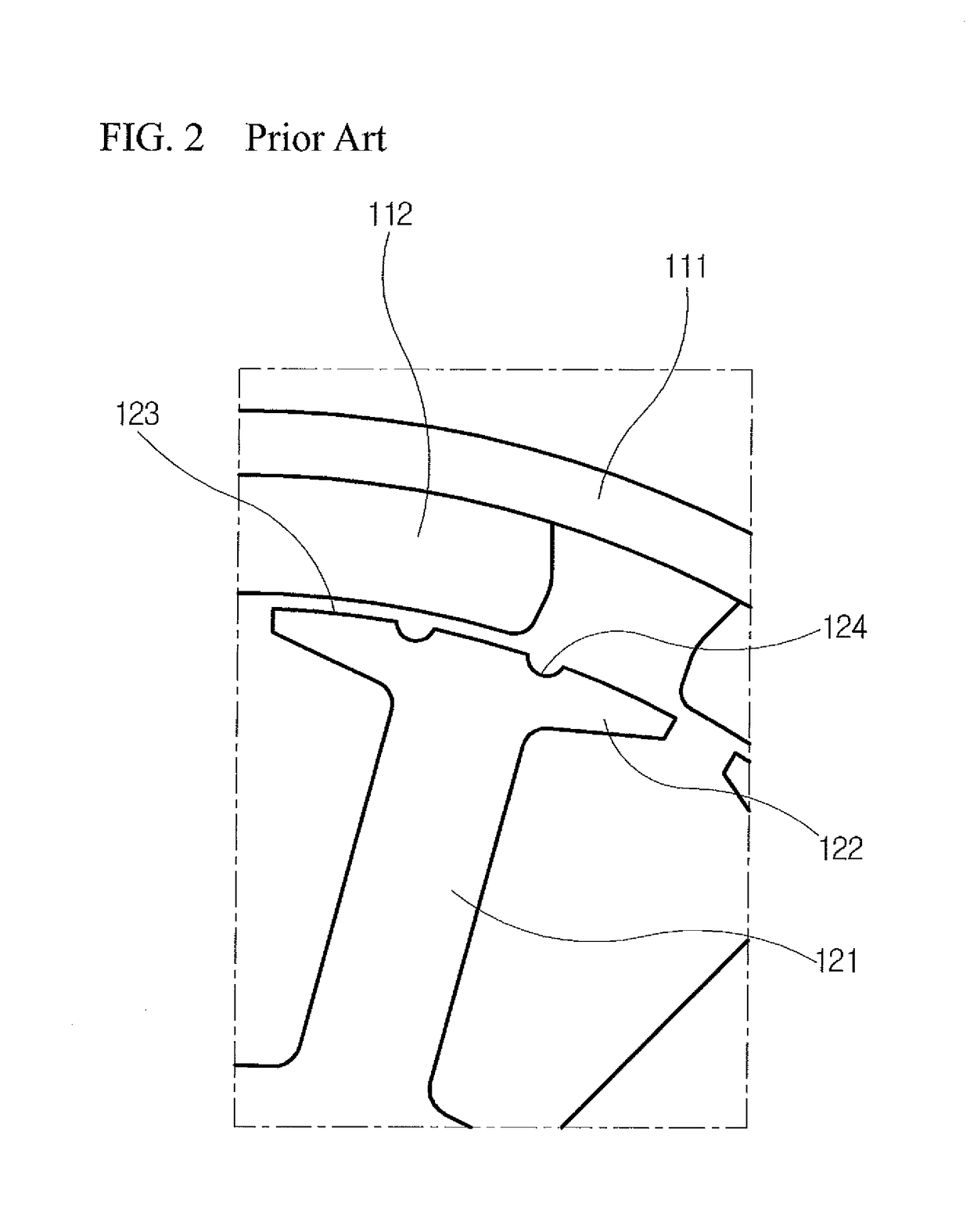
Brushless motor having a stator with teeth shaped to reduce cogging torque
a brushless motor and stator technology, applied in the direction of dynamo-electric machines, electrical equipment, magnetic circuit shapes/forms/construction, etc., can solve the problems of torque ripple, mechanical or electrical noise, vibration and noise, etc., to reduce the rate of variation in magnetic resistance and reduce cogging torque
- Summary
- Abstract
- Description
- Claims
- Application Information
AI Technical Summary
Benefits of technology
Problems solved by technology
Method used
Image

Examples
Embodiment Construction
[0040]Hereinafter, exemplary embodiments of the present invention will be described in detail with reference to the attached drawings.
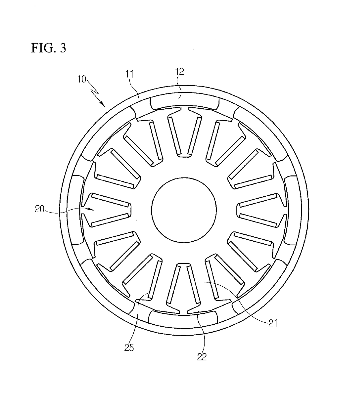
[0041]Referring to FIGS. 3 and 4, a brushless motor according to an embodiment of the present invention includes a rotor 10 in which permanent magnets 12 are provided on an inner circumferential surface of a rotor core 11, and a stator 20 in which teeth 22 are provided on respective outer ends of stator cores 21 around each of which a coil 25 is wound.
[0042]Each of the teeth 22 extends in a circumferential direction of the rotor core 11.
[0043]Each of the teeth 22 is configured such that the distance between each of facing surfaces 23 that face the permanent magnet 12 and an inner circumferential surface of the permanent magnet 12 is increased from the center of the tooth 22 to opposite ends thereof.
[0044]The facing surfaces 23 of the tooth 22 are formed to be symmetrical with each other based on a center line C of the corresponding stator core 21 in s...
PUM
 Abstract
Description
Claims
Application Information